Vertebral body spacer

a technology for vertebral bodies and spacers, applied in the field of vertebral body spacers, can solve the problems of insufficient amount of bone to be grafted, inability to harvest autologous bone, and inability to fusing between vertebral bodies, so as to prevent the vertebral body spacer and graft bone more reliably and quickly

Inactive Publication Date: 2013-10-17
MITSUBISHI MATERIALS CORP
View PDF5 Cites 34 Cited by
  • Summary
  • Abstract
  • Description
  • Claims
  • Application Information

AI Technical Summary

Benefits of technology

[0034]According to the vertebral body spacer of the present invention, it is capable of maintaining the appropriate size between the vertebral bodies (intervertebral space). Further, it is possible to reliably prevent the vertebral body spacer from being broken irrespective of the cases and the position of the intervertebral space, and thereby capable of achieving the bone fusion between the vertebral body spacer and the vertebral bodies promptly.
[0035]Further, by inserting the vertebral body spacer into the intervertebral space, it is ensured to obtain a space for filling a filler into the intervertebral space. Therefore, by filling, for example, a grafted bone into such a space, it is possible to achieve the bone fusion between the vertebral bodies through the vertebral body spacer and the grafted bone more reliably and promptly.

Problems solved by technology

However, in a case where only bone grafting into the intervertebral space is carried out, there is a possibility that unstable fusing between the vertebral bodies are caused by resorption of a grafted bone until bone fusion is achieved.
Further, an amount capable of harvesting an autologous bone is limited, so that there is a possibility that a bone to be grafted is not acquired in a sufficient amount.
However, it is impossible for the vertebral body spacer having the porosity falling within such a range to withstand stress on the vertebral body spacer depending on a body type of a patient to which the spacer is to be applied and a position of an intervertebral space such as lumbar vertebra and cervical vertebra.
As a result, there is a fear that the vertebral body spacer is broken by the stress.

Method used


Image

  • Vertebral body spacer
  • Vertebral body spacer
  • Vertebral body spacer

Examples


first embodiment

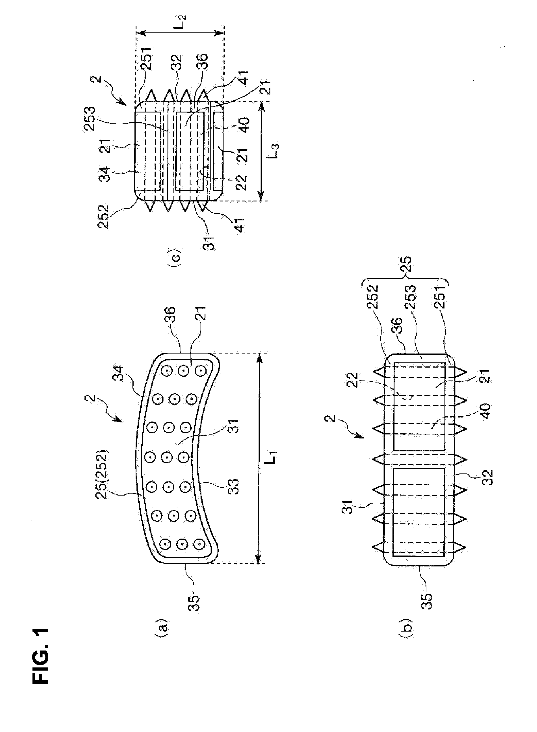
[0043]First, description will be made on a first embodiment of the vertebral body space according to the present invention.

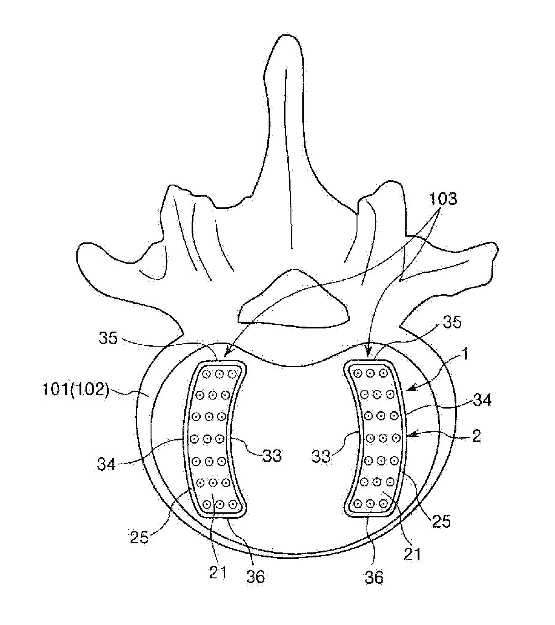
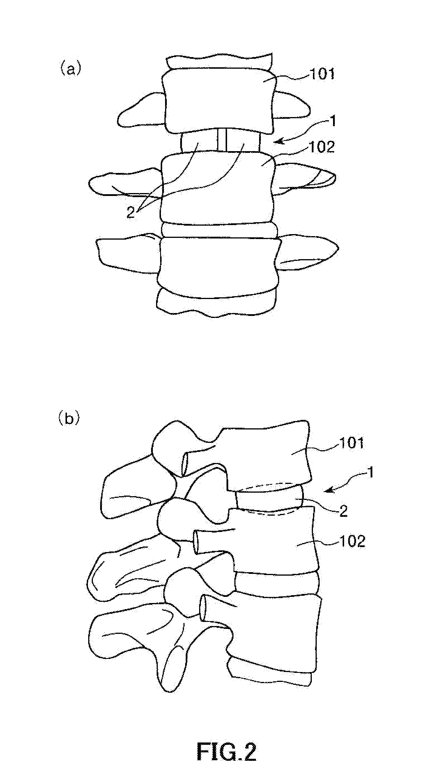
[0044]FIG. 1 is a plan view (a), a front view (b) and a side view (c) which show the first embodiment of a block body constituting the vertebral body spacer of the present invention. FIG. 2 and FIG. 3 are a view showing a used state of the vertebral body spacer of the present invention, respectively.

[0045]In the following description, it is to be noted that a state of inserting the vertebral body spacer between vertebral bodies of a case (patient) is defined as a basic state, thereby defining a position thereof, unless it is explicitly stated otherwise.

[0046]Specifically, a ventral side of the patient (namely, a right side in each of FIG. 1(a), FIG. 1(b) and FIG. 2(b), a near side in each sheet of FIG. 1(c) and FIG. 2(a), and a lower side in FIG. 3) will be referred to as “front”, and a dorsal side of the patient (namely, a left side in each of FIG. 1(a), FIG. 1...

second embodiment

[0112]Next, description will be made on a second embodiment of a vertebral body space according to the present invention.

[0113]FIG. 4 is a plan view (a), a front view (b) and a side view (c) which show the second embodiment of a block body constituting the vertebral body spacer of the present invention.

[0114]In the following description, the description will be made on a block body 2 shown in FIG. 4. The description will be made by focusing on different points from the block body 2 shown in FIG. 1 to FIG. 3 and the description on the common points is omitted.

[0115]The block body 2 shown in FIG. 4 is the same as the block body 2 shown in FIG. 1 to FIG. 3, except that a shape of the whole thereof is different.

[0116]In the present embodiment, both a first surface 31 and a second surface 32 constitute a curved convex surface, except an area in which projection portions 41 are provided. The first surface 31 and the second surface 32 are connected to each other at an end portion on a fron...

third embodiment

[0120]Next, description will be made on a third embodiment of a vertebral body space according to the present invention.

[0121]FIG. 5 is a plan view (a), a front view (b) and a side view (c) which show the third embodiment of a block body constituting the vertebral body spacer of the present invention. FIG. 6 is a view showing a used state of the third embodiment of the vertebral body spacer of the present invention.

[0122]In the following description, the description will be made on a block body 2 shown in FIGS. 5 and 6. The description will be made by focusing on different points from the block body 2 shown in FIG. 1 to FIG. 3 and the description on the common points is omitted.

[0123]The block body 2 shown in FIG. 5 is the same as the block body 2 shown in FIG. 1 to FIG. 3, except that a connecting portion 50 of rotatably connecting a pair of block bodies 2 to each other is provided with the pair of block bodies 2.

[0124]In the present embodiment, the connecting portion 50 has a plat...


PUM

PropertyMeasurementUnit
porosityaaaaaaaaaa
lengthaaaaaaaaaa
lengthaaaaaaaaaa

Abstract

A vertebral body spacer of the present invention is used by being inserted between a vertebral body and a vertebral body (intervertebral space). The vertebral body spacer has a block body constituted of titanium or a titanium alloy as a main component thereof, and provided with a pair of contact surfaces to be made contact with the vertebral body and the vertebral body. The block body includes needle parts formed into a needle shape having both end portions and a porous part having through holes passing through the porous part in a thickness direction thereof, and a porosity of at least a surface of the porous part is larger than a porosity of each of the needle parts. The needle parts are inserted into the through holes so that the both end portions are projected from the contact surfaces.

Description

TECHNICAL FIELD[0001]The present invention relates to a vertebral body spacer.RELATED ART[0002]Spinal canal stenosis is caused by degeneration of an intervertebral disk interposed between adjacent vertebral bodies (intervertebral space), degenerative facet joint disease, secondary deformation of a vertebral body, spinal deformation, or the like, and results in cauda equina / nerve root disorders.[0003]One approach for treating such spinal canal stenosis includes interbody fusion in which a degenerated intervertebral disk is removed from between the adjacent vertebral bodies, and then used is an vertebral body fusion surgery of fusing the vertebral bodies by implanting an autologous bone into an intervertebral space in which the intervertebral disk has been removed.[0004]However, in a case where only bone grafting into the intervertebral space is carried out, there is a possibility that unstable fusing between the vertebral bodies are caused by resorption of a grafted bone until bone f...

Claims


Application Information

Patent Timeline
Patent Type & Authority Applications(United States)
IPC IPC(8): A61F2/44
CPCA61F2/442A61F2/44A61F2/4465A61F2002/30011A61F2002/30224A61F2002/30471A61F2002/30492A61F2002/30616A61F2002/30841A61F2002/30892A61F2002/30967A61F2002/3097A61F2002/30971A61F2002/448A61F2310/00023A61F2310/00431A61F2310/00443A61F2310/00485A61F2310/00491A61F2310/00497A61F2310/00514A61F2310/00532A61F2310/00544A61F2310/00562A61F2310/00976A61F2002/30451A61F2002/30433A61F2002/30593A61F2/30771A61F2/4455A61F2002/3092
Inventor MATSUMOTO, TOSHIODAIGO, YUZOOHMORI, SHINICHIKATO, KOMEI
Owner MITSUBISHI MATERIALS CORP
Why Eureka
Try Eureka