Vertebral body spacer

a technology for vertebral bodies and spacers, applied in the field of vertebral body spacers, can solve the problems of insufficient amount of bone to be grafted, inability to harvest autologous bone, and inability to stabilize the fusing between vertebral bodies, so as to prevent the fusing of vertebral bodies and achieve the effect of grafting bone more reliably and quickly

Inactive Publication Date: 2013-10-17
MITSUBISHI MATERIALS CORP
View PDF4 Cites 22 Cited by
  • Summary
  • Abstract
  • Description
  • Claims
  • Application Information

AI Technical Summary

Benefits of technology

[0036]This makes it possible to change a position of a pair of block bodies, namely to position the pair of block bodies in a state of spacing front ends and back ends of the pair of block bodies from each other and/or approaching them to each other. Therefore, it is possible to provide an appropriate cure depending on cases by using such a vertebral body spacer.
[0037]According to the vertebral body spacer of the present invention, it is capable of maintaining the appropriate size between vertebral bodies (intervertebral space). Further, it is possible to reliably prevent the vertebral body spac

Problems solved by technology

However, in a case where only bone grafting into the intervertebral space is carried out, there is a possibility that unstable fusing between the vertebral bodies is caused by resorption of a grafted bone until bone fusion is achieved.
Further, an amount capable of harvesting an autologous bone is limited, so that there is a possibility that a bone to be grafted is not acquired in a sufficient amount.
However, it is

Method used


Image

  • Vertebral body spacer
  • Vertebral body spacer
  • Vertebral body spacer

Examples


first embodiment

[0052]First, description will be made on a first embodiment of a vertebral body space according to the present invention.

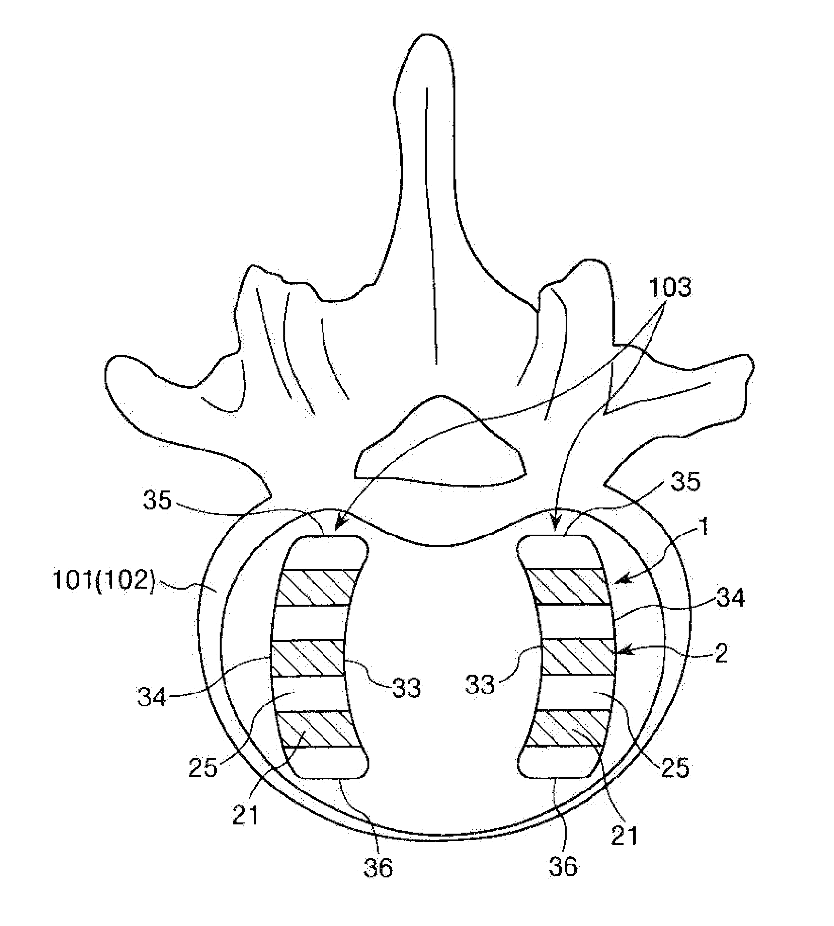
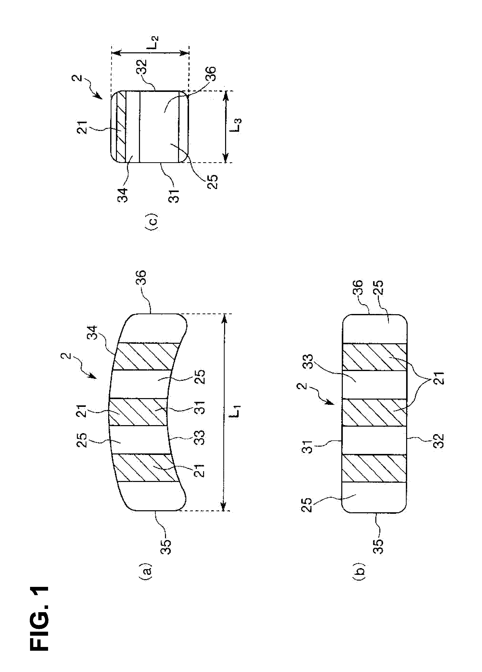
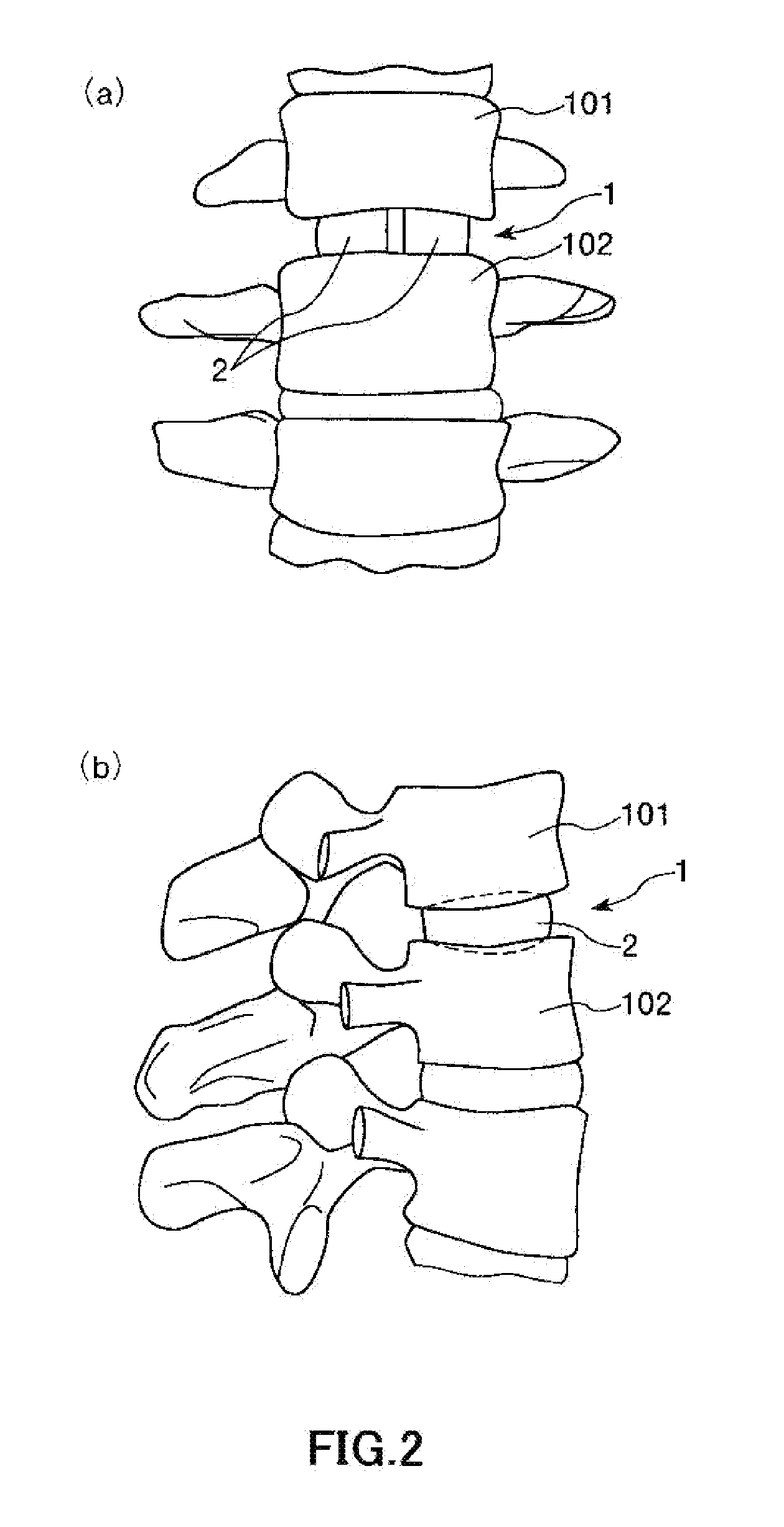
[0053]FIG. 1 is a plan view (a), a front view (b) and a side view (c) which show the first embodiment of a block body constituting the vertebral body spacer of the present invention. FIG. 2 and FIG. 3 are a view showing a used state of the first embodiment of the vertebral body spacer of the present invention, respectively.

[0054]In the following description, it is to be noted that a state of inserting the vertebral body spacer between vertebral bodies of a case (patient) is defined as a basic state, thereby identifying a position thereof, unless it is explicitly stated otherwise.

[0055]Specifically, a ventral side of the patient (namely, a right side in each of FIG. 1(a), FIG. 1(b) and FIG. 2(b), a near side in each sheet of FIG. 1(c) and FIG. 2(a), and a lower side in FIG. 3) will be referred to as “front”, and a dorsal side of the patient (namely, a left side in ...

second embodiment

[0116]Next, description will be made on a second embodiment of a vertebral body space according to the present invention.

[0117]FIG. 4 is a plan view (a), a front view (b) and a side view (c) which show the second embodiment of a block body constituting the vertebral body spacer of the present invention.

[0118]In the following description, the description will be made on a block body 2 shown in FIG. 4. The description will be made by focusing on different points from the block body 2 shown in FIG. 1 to FIG. 3 and the description on the common points is omitted.

[0119]The block body 2 shown in FIG. 4 is the same as the block body 2 shown in FIG. 1 to FIG. 3, except that shapes of the dense sheets 25 and the porous sheets 21 are different and a direction in which the dense sheets 25 and the porous sheets 21 are arranged is different.

[0120]In the present embodiment, the block body 2 is constituted from three dense sheets 25 and two porous sheets 21. One porous sheet 21 is sandwiched betwe...

third embodiment

[0123]Next, description will be made on a third embodiment of a vertebral body space according to the present invention.

[0124]FIG. 5 is a plan view (a), a front view (b) and a side view (c) which show the third embodiment of a block body constituting the vertebral body spacer of the present invention.

[0125]In the following description, the description will be made on a block body 2 shown in FIG. 5. The description will be made by focusing on different points from the block body 2 shown in FIG. 1 to FIG. 3 and the description on the common points is omitted.

[0126]The block body 2 shown in FIG. 5 is the same as the block body 2 shown in FIG. 1 to FIG. 3, except that shapes of the dense sheets 25 and the porous sheets 21 are different and a direction in which the dense sheets 25 and the porous sheets 21 are arranged is different.

[0127]In the present embodiment, the block body 2 is constituted from three dense sheets 25 and two porous sheets 21. One porous sheet 21 is sandwiched between...


PUM

PropertyMeasurementUnit
Shapeaaaaaaaaaa

Abstract

A vertebral body spacer of the present invention is used by being inserted between a vertebral body and a vertebral body (intervertebral space). The vertebral body spacer has a block body constituted of titanium or a titanium alloy as a main component thereof, and provided with a pair of contact surfaces to be made contact with the vertebral body and the vertebral body. The block body includes dense sheets having a dense part on at least a surface thereof and porous sheets having a porous part on at least a surface thereof. The porous part has a larger porosity than a porosity of the dense part. Each of the porous sheets is sandwiched between the pair of dense sheets. According to the present invention, it is possible to maintain an appropriate size between the vertebral bodies (intervertebral space).

Description

TECHNICAL FIELD[0001]The present invention relates to a vertebral body spacer.RELATED ART[0002]Spinal canal stenosis is caused by degeneration of an intervertebral disk interposed between adjacent vertebral bodies (intervertebral space), degenerative facet joint disease, secondary deformation of a vertebral body, spinal deformation, or the like, and results in cauda equina / nerve root disorders.[0003]One approach for treating such spinal canal stenosis includes interbody fusion in which a degenerated intervertebral disk is removed from between the adjacent vertebral bodies, and then used is an vertebral body fusion surgery of fusing the vertebral bodies by implanting an autologous bone into an intervertebral space in which the intervertebral disk has been removed.[0004]However, in a case where only bone grafting into the intervertebral space is carried out, there is a possibility that unstable fusing between the vertebral bodies is caused by resorption of a grafted bone until bone fu...

Claims


Application Information

Patent Timeline
IPC IPC(8): A61F2/44
CPCA61F2/442A61F2310/00976A61F2002/30011A61F2002/30013A61F2002/30471A61F2002/30472A61F2002/30492A61F2002/30616A61F2002/30841A61F2002/30892A61F2002/30967A61F2002/30968A61F2002/3097A61F2002/30971A61F2002/448A61F2310/00023A61F2310/00431A61F2310/00443A61F2310/00485A61F2310/00491A61F2310/00497A61F2310/00514A61F2310/00532A61F2310/00544A61F2310/00562A61F2/4465A61F2002/30433A61F2/44
Inventor MATSUMOTO, TOSHIODAIGO, YUZOOHMORI, SHINICHIKATO, KOMEI
Owner MITSUBISHI MATERIALS CORP
Why Eureka
Try Eureka