
Air conditioning system with multiple-effect evaporative condenser

a technology of evaporative condenser and air conditioning system, which is applied in the direction of indirect heat exchangers, lighting and heating apparatus, heating types, etc., can solve the problems of cumbersome maintenance procedures, waste of raw materials, and energy needed to pump the cooling water circulating between the cooling towers, and achieves enhanced heat exchange performance, increased saturated air temperature, and high efficiency

Active Publication Date: 2013-10-24
WONG LEE WA
View PDF6 Cites 39 Cited by
  • Summary
  • Abstract
  • Description
  • Claims
  • Application Information

AI Technical Summary

Benefits of technology

This patent describes a multiple-effect evaporative condenser that has several technical advantages. First, it eliminates the need for expensive and extensive piping and components between cooling towers and conventional central air conditioning systems. Second, it utilizes highly efficient heat exchanging pipes with a large area of heating surfaces for performing heat exchange between cooling water and refrigerant. Third, it includes multiple heat exchanging units that perform heat exchange in a multi-staged manner, which resolve inconsistent heat exchange problems in conventional cooling towers. Fourth, it increases the saturated air temperature at the air outlet to enhance heat exchange performance. Fifth, it provides a heat exchanger that efficiently facilitates heat exchange between refrigerant and water by using highly efficient heat exchanging pipes with a large contact surface area and outer heat exchanging fins for forming large heat exchanging surface area.

Problems solved by technology

There exist a number of disadvantages in association with the above-mentioned air conditioning system.
Such an extensive piping system requires cumbersome maintenance procedures and constitutes substantial waste of raw materials.
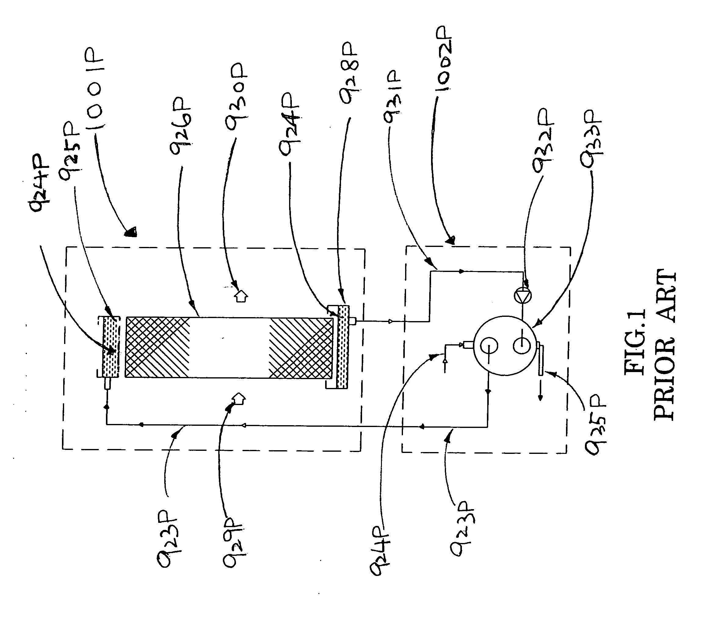
Moreover, since the ducts connecting the cooling tower 1001P and the condenser 1002P are very long in length, very great resistance will be developed within the ducts so that the energy needed to pump the cooling water circulating between the cooling tower 1001P and the condenser 1002P is necessarily wasted.
This substantially reduces the efficiency of the entire cooling tower air conditioning system.

Method used


Image

  • Air conditioning system with multiple-effect evaporative condenser
  • Air conditioning system with multiple-effect evaporative condenser
  • Air conditioning system with multiple-effect evaporative condenser

Examples


Embodiment Construction

[0094]Referring to Referring to FIG. 3 to FIG. 6 of the drawings, a multiple-effect evaporative condenser 100 for an air conditioning system according to a preferred embodiment of the present invention is illustrated. The air conditioning system is for cooling a predetermined space, such as a particular space within a building, by using a predetermined amount of cooling water 1 and refrigerant 3 (as shown in FIG. 8). The components of the air conditioning system will be discussed one by one below. However, it is worth noting that some of the components are by themselves patentably distinctive and may be used in applications other than air conditioning systems.

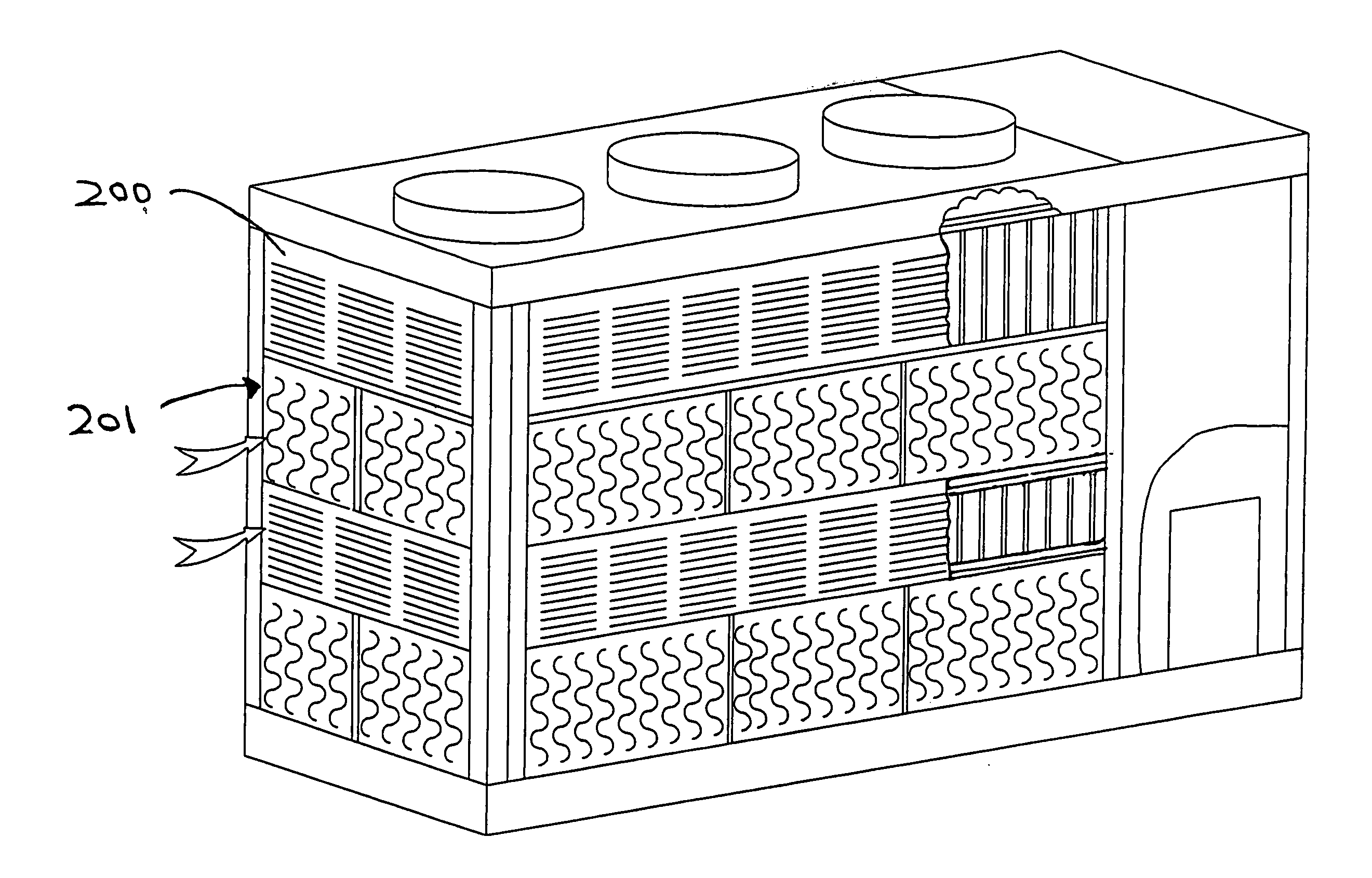
[0095]The multiple-effect evaporative condenser 100 comprises a pumping device 10 adapted for pumping the cooling water 1 at a predetermined flow rate, a tower housing 200 having an air inlet 201 and an air outlet 202, wherein an air draft is drawn between the air inlet 201 and the air outlet 202.

[0096]The multiple-effect evapo...


PUM

PropertyMeasurementUnit
Temperatureaaaaaaaaaa
Flow rateaaaaaaaaaa
Diameteraaaaaaaaaa

Abstract

An air conditioning system includes a multiple effect evaporative condenser, at least one compressor, at least one heat exchanger, an expansion valve, and at least one multiple-effect evaporative condensers. The multiple effect evaporative condenser and the heat exchanger utilize a highly efficient heat exchanging pipe for performing heat exchange between water and refrigerant.

Description

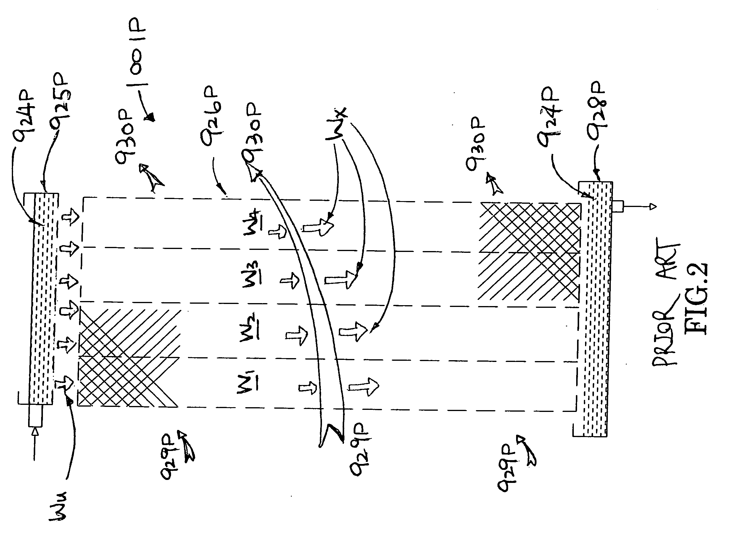
BACKGROUND OF THE PRESENT INVENTION[0001]1. Field of Invention[0002]The present invention relates to an air conditioning system, and more particularly to an air conditioning system utilizing a multiple effect evaporative condenser for effectively and efficiently cooling refrigerant.[0003]2. Description of Related Arts[0004]Referring to FIG. 1 to FIG. 2 of the drawings, a conventional condenser 1002P and a conventional cooling tower 1001P for a central air conditioning system is illustrated. The conventional cooling tower 1001P and the conventional condenser 1002P are connected through water pipes 931P, 923P in which cooling water 924P is pumped by a pumping device 932P to circulate between the cooling tower 1001P and the condenser 1002 through the water pipes 931P, 923P. The cooling tower 1001P is usually installed on an exterior of a building, such as on the roof of the building.[0005]Vaporous refrigerant (coming from a compressor of the central air conditioning system) having an e...

Claims


Application Information

Patent Timeline
IPC IPC(8): F28D15/00F28F1/42F28F19/02F25B41/00
CPCF25B39/04F28F1/36F28F1/42F24F5/001F24F13/30F28D5/02F25B2339/041F28F25/04F24F2013/225F28B1/02F28B9/04F28C1/14Y02B30/70F25B1/005F28F1/12F24F5/0007
Inventor WONG, LEE WA
Owner WONG LEE WA
Learn More