Chemical vapor deposition chamber cleaning with molecular fluorine

a technology of molecular fluorine and chemical vapor deposition chamber, which is applied in the direction of cleaning hollow articles, coatings, chemistry apparatus and processes, etc., can solve the problems of increasing equipment and operation costs, reducing the life of equipment and parts, and causing damage to the equipment and parts

Inactive Publication Date: 2013-10-24
CIGAL JEAN CHARLES +4
View PDF2 Cites 3 Cited by
  • Summary
  • Abstract
  • Description
  • Claims
  • Application Information

AI Technical Summary

Benefits of technology

[0009]The present invention provides improved methods and apparatus for the cleaning PECVD chambers that overcome the disadvantages of the prior art methods and apparatus. In particular, the present invention utilizes molecular fluorine for cleaning of the chamber.

Problems solved by technology

However, in-situ plasma activation can result in plasma induced damage and reduction of equipment and parts lifetime.
Further, high pressures need to be avoided because of the risk of arcing.
However, using a remote plasma source requires additional equipment that adds considerable equipment and operations cost.
Further, gas flow is often limited by the parameters of the remote plasma source thereby increasing cleaning time and cost.
A further chamber cleaning method comprises thermally cleaning the chamber at high temperatures, typically 600° C. to 900° C. or higher when using gases such as NF3 or SF6 that require temperatures of about 900° C. These high temperatures are usually much higher than the temperatures needed for the deposition processes and the required temperature adjustments add to the cleaning time and cost.
The high temperatures and high pressures required for this cleaning method are significantly different than the temperature and pressure employed during the deposition processes that therefore again add to cleaning time and cost because of the required temperature and pressure adjustments.
Further, this cleaning method may require additional pumping systems therefore adding equipment and operational costs.
All of the above cleaning methods exhibit difficulty reaching shielded areas of the chamber, because the volume of plasma is directly related to the power and ability to sustain an RF field.
Therefore, all areas of the chamber can not be reached or cleaned effectively, particularly those areas that are shielded from the RF field.

Method used


Image

  • Chemical vapor deposition chamber cleaning with molecular fluorine
  • Chemical vapor deposition chamber cleaning with molecular fluorine
  • Chemical vapor deposition chamber cleaning with molecular fluorine

Examples


Embodiment Construction

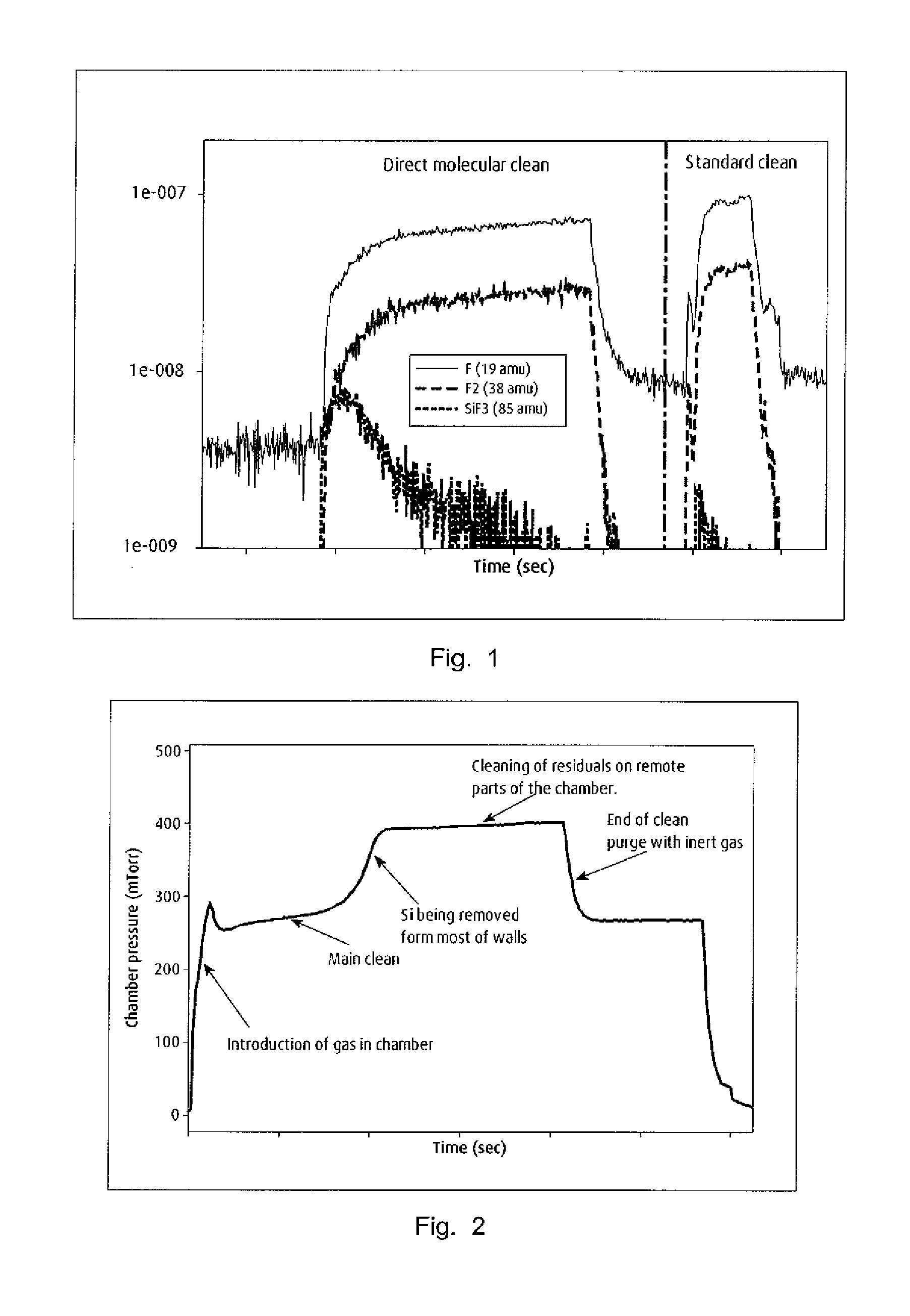
[0015]The present invention uses molecular fluorine for PECVD chamber cleaning. These PECVD chambers are used to deposit silicon (both amorphous and microcrystalline) for photovoltaic devices. Generally, the deposition processes are carried out at temperatures as low as 160° C. and do not need plasma activation, either in-situ or remote.

[0016]For cleaning of the PECVD chamber according to the present invention, fluorine is introduced to the chamber at a predetermined pressure. Cleaning of the chamber is accomplished solely by the reaction of molecular fluorine with deposited silicon on the interior walls and equipment of the PECVD chamber. The time needed for cleaning is dependent on the predetermined pressure and surface temperature.

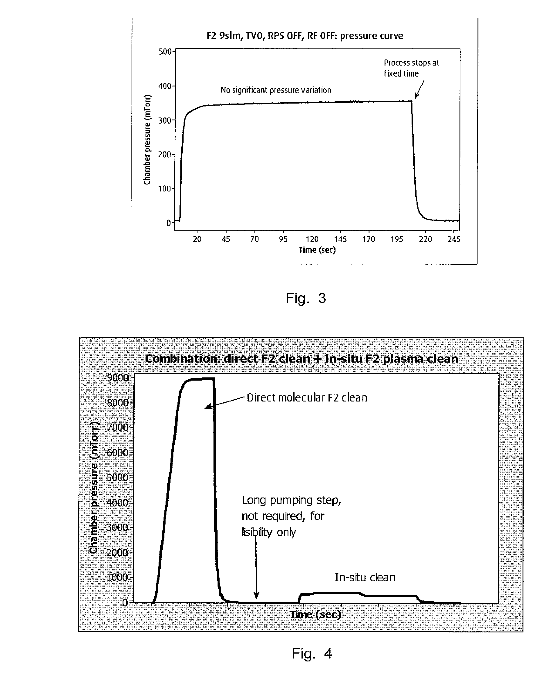
[0017]In accordance with the present invention, it has been found that it is possible to clean the PECVD chamber at base pressure obtained by having the valves from the chamber to the pump foreline fully open. Pressures as low as 350 mTorr (0.47 mbar) w...


PUM

PropertyMeasurementUnit
fixed pressureaaaaaaaaaa
temperatureaaaaaaaaaa

Abstract

Methods and apparatus for the cleaning PECVD chambers that utilize molecular fluorine as the cleaning material.

Description

FIELD OF THE INVENTION[0001]The present invention relates to new methods for the cleaning chemical vapor deposition (CVD) chambers, particularly plasma-enhanced chemical vapor deposition (PECVD) chambers and to apparatus therefore.BACKGROUND OF THE INVENTION[0002]Amorphous and microcrystalline thin films are used to fabricate photovoltaic devices and are generally deposited using chemical vapor deposition techniques. In particular PECVD methods deposit thin films from a gas state to a solid state onto the surface of a substrate by injecting precursor reacting gases into a PECVD chamber and then splitting the gases into active ions or radicals (i.e. dissociated neutral reactive elements) using a plasma created by radio frequency (RF) or DC discharge. The manufacture of devices using PECVD methods includes the depositing of thin films of silicon, silicon oxide, silicon nitride, metals oxides, and others. These deposition processes leave deposits in the chamber that must be periodicall...

Claims


Application Information

Patent Timeline
Patent Type & Authority Applications(United States)
IPC IPC(8): B08B7/00
CPCB08B7/0021B08B7/00B08B7/0035C23C16/4405B08B9/00H01L21/31C23C16/44
Inventor CIGAL, JEAN-CHARLESHWANG, YING-SIANGSTOCKMAN, PAUL ALANHOGLE, RICHARDPETRI, STEFAN
Owner CIGAL JEAN CHARLES
Why Eureka
Try Eureka