Conductive mesh for composite tube for fluid delivery system

Active Publication Date: 2013-10-24
EATON INTELLIGENT POWER LIMITED
View PDF9 Cites 7 Cited by
  • Summary
  • Abstract
  • Description
  • Claims
  • Application Information

AI Technical Summary

Benefits of technology

[0024]As mentioned with respect to the integral or one piece fiber knitted pattern, delamination is avoided at tube intersection points or other areas where separate tube sections are joined since the matrix material can be applied continuously across these intersection points. A continuously extending tubular fiber in combination with the continuously applied matrix material avoids all laminated seams or overlapping areas.
[0025]It is well known that most composite tubes are formed on rigid inner mandrels having limited flexibility. This reduces the available geometries for a tube to be formed because ultimately, the mandrel must be removed from the interior of the tube section. In the present invention, the shape holding feature of a tube design is built into the underlying fiber pattern itself. This method therefore allows for use of a very flexible and collapsible inner mold such as the inflatable bladder. Nevertheless, a vacuum bag molding technique can be used for necessary internal and external compressed molding, while critical exterior features and varied end configurations can be held in place by modular exterior fixturing. The manufacturing method of the invention

Problems solved by technology

Various efforts have been made to isolate fuel lines to ensure the fuel lines maintain the desired electrical properties; however, traditional fuel lines are unable to accommodate wide electrical performance requirements when comparing an event such as a lightning strike versus slow but incremental static buildup.
One particular problem associated with composite tubing is delamination that can occur between joined sections of tubes or layers among tubes.
Although initially these overlapping edges may provide an adequate structural connection, vibration and chemical degradation by contact of the fuel with the composite material eventually results in some degree of delamination.
In these cases, it may be impractical or impossible to use mechanical couplers at each junction due to weight and size constraints.
Another limitation associated with composite tubes that ma

Method used


Image

  • Conductive mesh for composite tube for fluid delivery system
  • Conductive mesh for composite tube for fluid delivery system
  • Conductive mesh for composite tube for fluid delivery system

Examples


Embodiment Construction

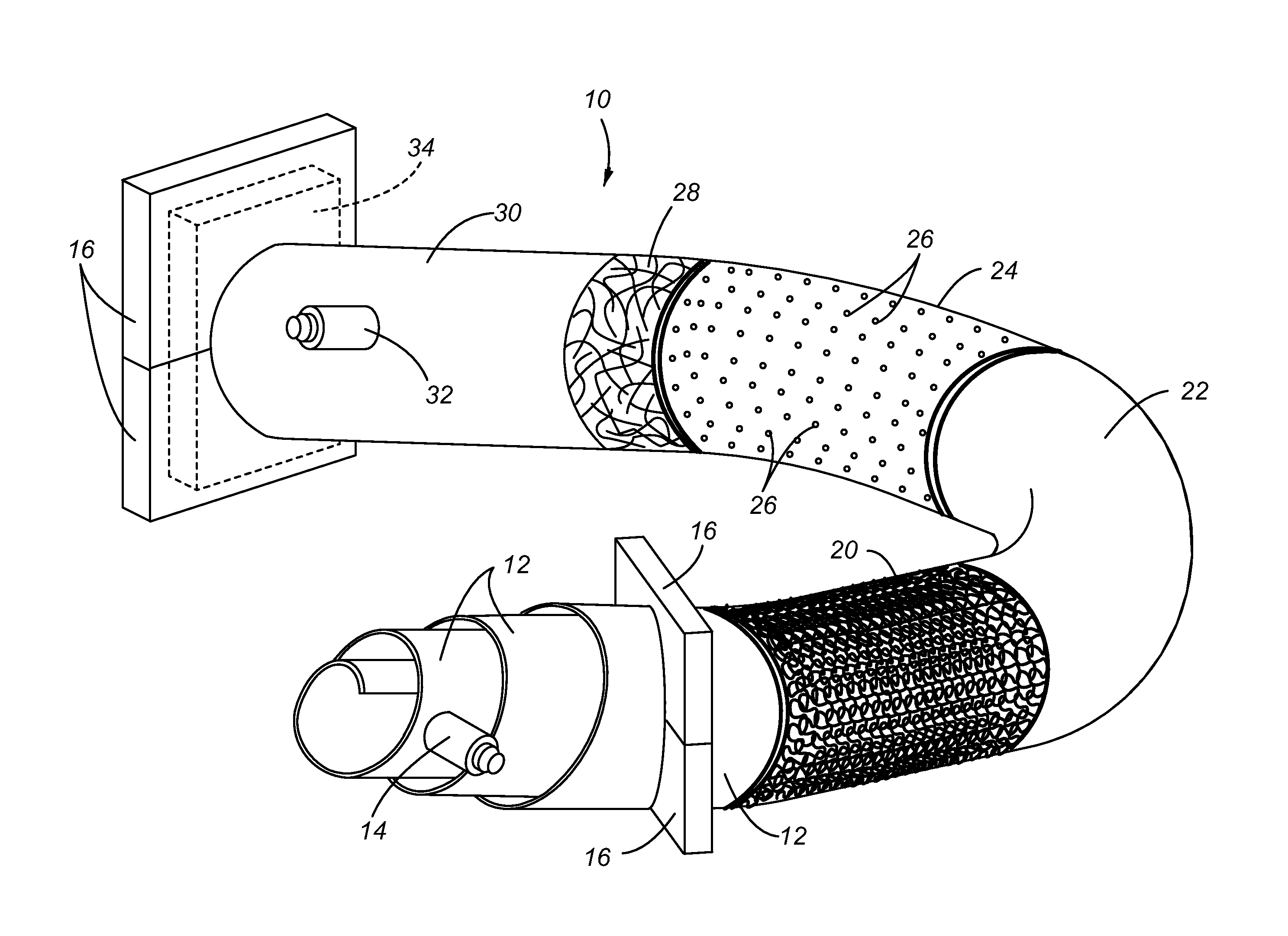
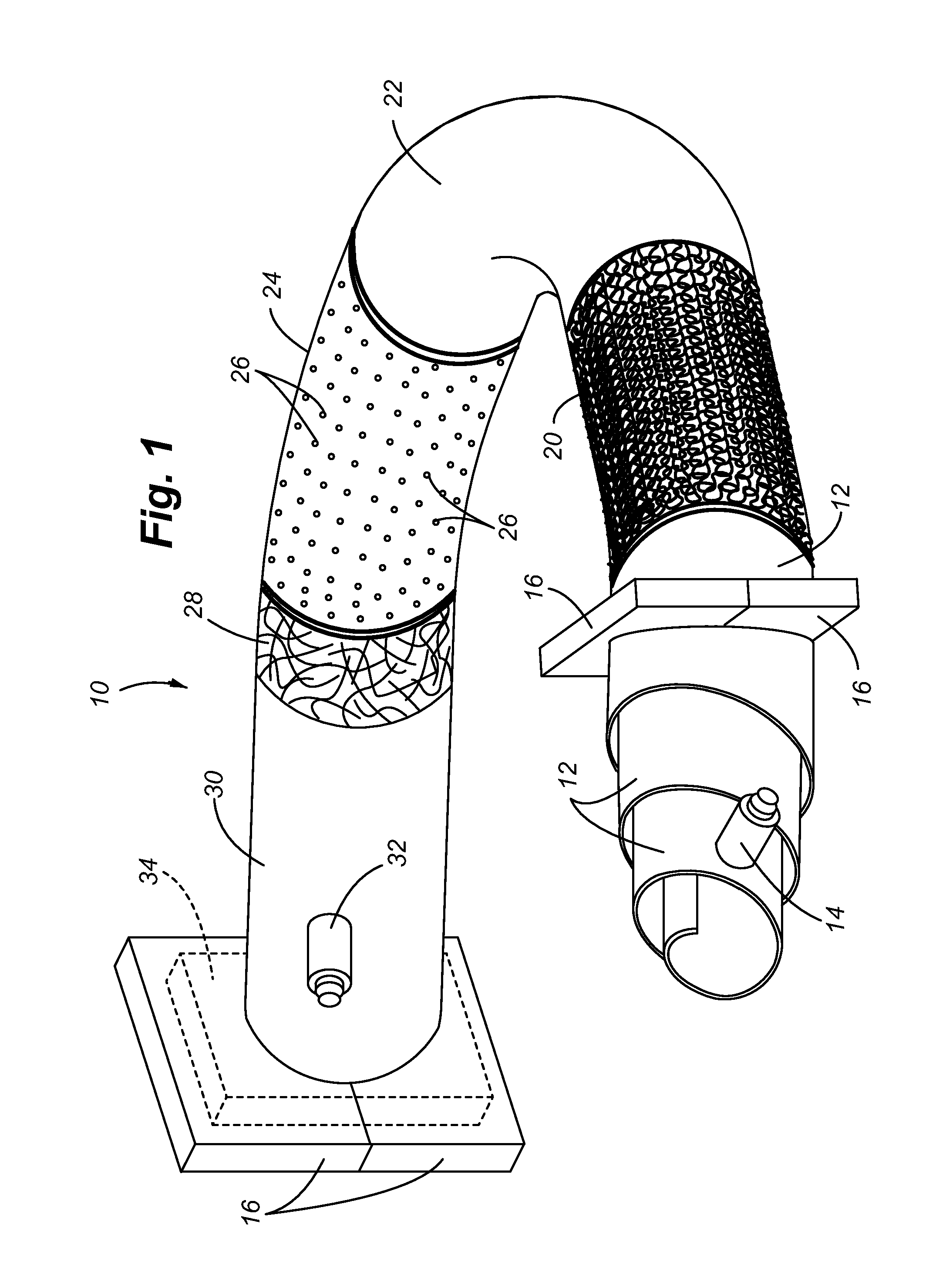
[0049]Referring to FIG. 1, a method of manufacturing the composite tube of the present invention is illustrated. The composite tube 10 is formed by a vacuum bag molding process. For illustrative purposes, the successive layers of material are shown as exposed. First, a spiraled inner bladder 12 is placed within the interior opening of a knitted reinforcement layer 20. The tubular knitted pattern formed for the reinforcement layer 20 is constructed with the previously described knitted pattern having a selected group of fibers formed in a plurality of loops. The inner bladder 12 is inflated through inflation port 14, in order to expand the knitted reinforcement layer 20 to a desired diameter or shape. Additionally, the knitted reinforcement layer 20 is shown as having a bend. The reinforcement layer can be knitted with the bend. This type of knitting to produce a bend could be similar to the formation of a bend in a woven garment, such as the heel portion of a knitted sock or slipper...


PUM

PropertyMeasurementUnit
Lengthaaaaaaaaaa
Thicknessaaaaaaaaaa
Electrical conductivityaaaaaaaaaa

Abstract

An electrically tuned composite tube comprises a tubular arrangement of a knitted reinforcement layer. Selected knitted patterns provide desired density or spacing between fibers of the reinforcement layer. A mesh element is also incorporated in the tube construction to precisely control resistivity and conductivity performance characteristics by selecting the mesh element from one or more conductive or non-conductive fibers or wires. The mesh element may include a tubular arrangement of fiber or wire provided in a knitted pattern or a woven pattern. A matrix material is applied over the knitted reinforcement layer and mesh element, and is allowed to cure for a single matrix layer. Alternatively, a first tube can be constructed with only the knitted reinforcement layer and matrix material, and the mesh element is added afterwards with another layer of matrix material applied over the exterior surface of the first tube.

Description

CROSS REFERENCE TO RELATED APPLICATIONS[0001]This application is a continuation-in-part application of co-pending application Ser. No. 12 / 983,069 filed on 31 Dec. 2010 and entitled: Composite Tube For Fluid Delivery System, of which said application is hereby incorporated by reference in its entirety.FIELD OF THE INVENTION[0002]The present invention relates to a composite tube used in fluid delivery systems, and more particularly, to a composite tube incorporating a selected conductive or non-conductive mesh element to tune the conductivity of the composite tube, and the mesh element and composite tube combination being especially adapted for use in fluid delivery of fuel in vehicles or aircraft.BACKGROUND OF THE INVENTION[0003]Polymer based compositions are becoming increasingly used in a variety of different technological applications to include vehicle and aerospace applications. Polymer based composites are used in not only structural applications, but also in construction of sy...

Claims


Application Information

Patent Timeline
IPC IPC(8): H01B5/12H01B13/00
CPCH01B5/12H01B13/00B29C70/446B29C70/882B29L2023/22F16L9/125F16L11/086F16L11/127F02M37/0017D04B1/225Y10T29/49117D10B2401/16D10B2505/02D10B2403/0333
Inventor GAUCKLER, ANDREAS MANFREDSTATLER, III, RICHARD L.BREAY, CLIFTON P.
Owner EATON INTELLIGENT POWER LIMITED
Why Eureka
Try Eureka