
Semiconductor light source lighting circuit

Active Publication Date: 2013-10-24
KOITO MFG CO LTD
View PDF3 Cites 16 Cited by
  • Summary
  • Abstract
  • Description
  • Claims
  • Application Information

AI Technical Summary

Benefits of technology

The patent text describes a semiconductor light source that can suppress the fluctuation of its current even when the circuit is digitized. The technical effect of this invention is to provide a more stable and consistent lighting circuit.

Problems solved by technology

However, as a result of the digitization, there may be a possibility that an oscillation occurs in the current flowing through the LED by an interaction between a counting operation in the feedback control and a switching operation of the switching regulator.

Method used


Image

  • Semiconductor light source lighting circuit
  • Semiconductor light source lighting circuit
  • Semiconductor light source lighting circuit

Examples


Embodiment Construction

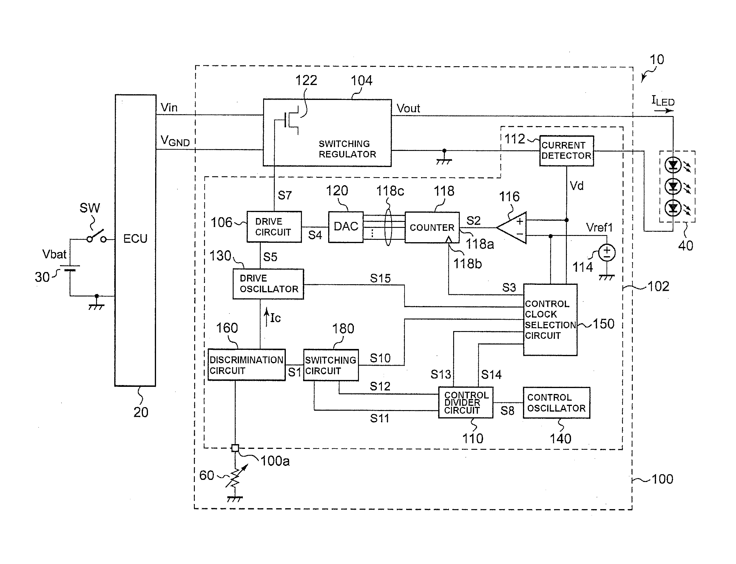
[0015]The same or similar components, members and signals shown in each drawing are denoted by the same reference numerals and a duplicated description thereof is appropriately omitted. In each drawing, some of the members that are not important for descriptive purposes are omitted. In addition, the reference numerals used to denote voltage, current or resistance or the like are sometimes used to represent respective values of voltage, current or resistance as necessary.

[0016]In this specification, a “state in which a member A is connected to a member B” includes not only the case where the member A and the member B are physically directly connected to each other but also the case where the member A and the member B are indirectly connected to each other via another member which does not affect the electric connection state therebetween. Likewise, a “state in which a member C is provided between a member A and a member B” includes not only the case where the member A and the member ...


PUM


Abstract

A semiconductor light source lighting circuit is provided with: a switching regulator that generates a drive current of a semiconductor light source using a switching element; and a control circuit that controls ON / OFF of the switching element. The control circuit is provided with: a comparator that compares the drive current and a target value; a counter that counts a digital value in a count direction determined by a comparison result of the comparator; a digital-analog converter that converts the digital value into an analog signal; and a drive circuit that controls the ON / OFF of the switching element based on the analog signal. The counter counts the digital value at a speed determined by an ON / OFF cycle of the switching element.

Description

[0001]This application claims foreign priority from Japanese Patent Application No. 2012-096410 filed on Apr. 20, 2012, the entire contents of which are hereby incorporated by reference.BACKGROUND OF THE INVENTION[0002]1. Field of the Invention[0003]The invention relates to a semiconductor light source lighting circuit for lighting a semiconductor light source such as an LED (Light Emitting Diode).[0004]2. Related Art[0005]In recent years, an LED having a longer life and lower power consumption has been used as a vehicular lamp such as a headlamp, instead of a conventional halogen lamp having a filament. Since a degree of light emission (e.g. a brightness) of the LED depends on a current flowing through the LED, it is necessary to provide a lighting circuit for adjusting the current flowing through the LED in order to use the LED as a light source.[0006]Such a lighting circuit usually includes a switching regulator for generating the current flowing through the LED using a switching...

Claims


Application Information

Patent Timeline
IPC IPC(8): H05B33/08H05B44/00
CPCH05B33/0815H05B45/14H05B45/3725
Inventor KIKUCHI, SATOSHINAMBA, TAKANORIITO, MASAYASU
Owner KOITO MFG CO LTD
Learn More