
Single-eye stereoscopic imaging device, correction method thereof, and recording medium thereof

a stereoscopic imaging and correction method technology, applied in stereoscopic photography, instruments, television systems, etc., can solve the problems of single-eye 3d camera, difficult technique application, and inability to disclose shading correction details, etc., and achieve the effect of simple method

Inactive Publication Date: 2013-10-24
FUJIFILM CORP
View PDF12 Cites 18 Cited by
  • Summary
  • Abstract
  • Description
  • Claims
  • Application Information

AI Technical Summary

Benefits of technology

The present invention provides a single-eye stereoscopic imaging device that can correct the unique shading characteristics of such device using a simple method. The device can correct the shading in the horizontal and vertical directions caused by at least the imaging optical system and in the gradient direction of density unevenness caused by the pupil division of the pupil division unit. The device uses a one-dimensional correction table for shading correction, which reduces the need for memory capacity, calculation, or circuit size. The device can also perform shading correction for the main pixel and the sub-pixel with bilaterally symmetric shading characteristics using one one-dimensional correction table. Overall, the invention allows for easy correction of the unique shading characteristics of a single-eye stereoscopic imaging device.

Problems solved by technology

However, the technique disclosed in JP2008-270937A is based on application to a multi-eye camera including a plurality of imaging optical systems, but it is difficult to apply the technique to a single-eye 3D camera (single-eye stereoscopic imaging device) which uses a single imaging lens (imaging optical system), divides beams passing through the single imaging lens into a plurality of beams, and focuses the beams on a single imaging element (pupil division) to capture a stereoscopic image (hereinafter, referred to as a pupil division type).
In addition, JP2008-270937A does not disclose the details of shading correction.

Method used


Image

  • Single-eye stereoscopic imaging device, correction method thereof, and recording medium thereof
  • Single-eye stereoscopic imaging device, correction method thereof, and recording medium thereof
  • Single-eye stereoscopic imaging device, correction method thereof, and recording medium thereof

Examples


first embodiment

[0069][Overall Structure of Imaging Device]

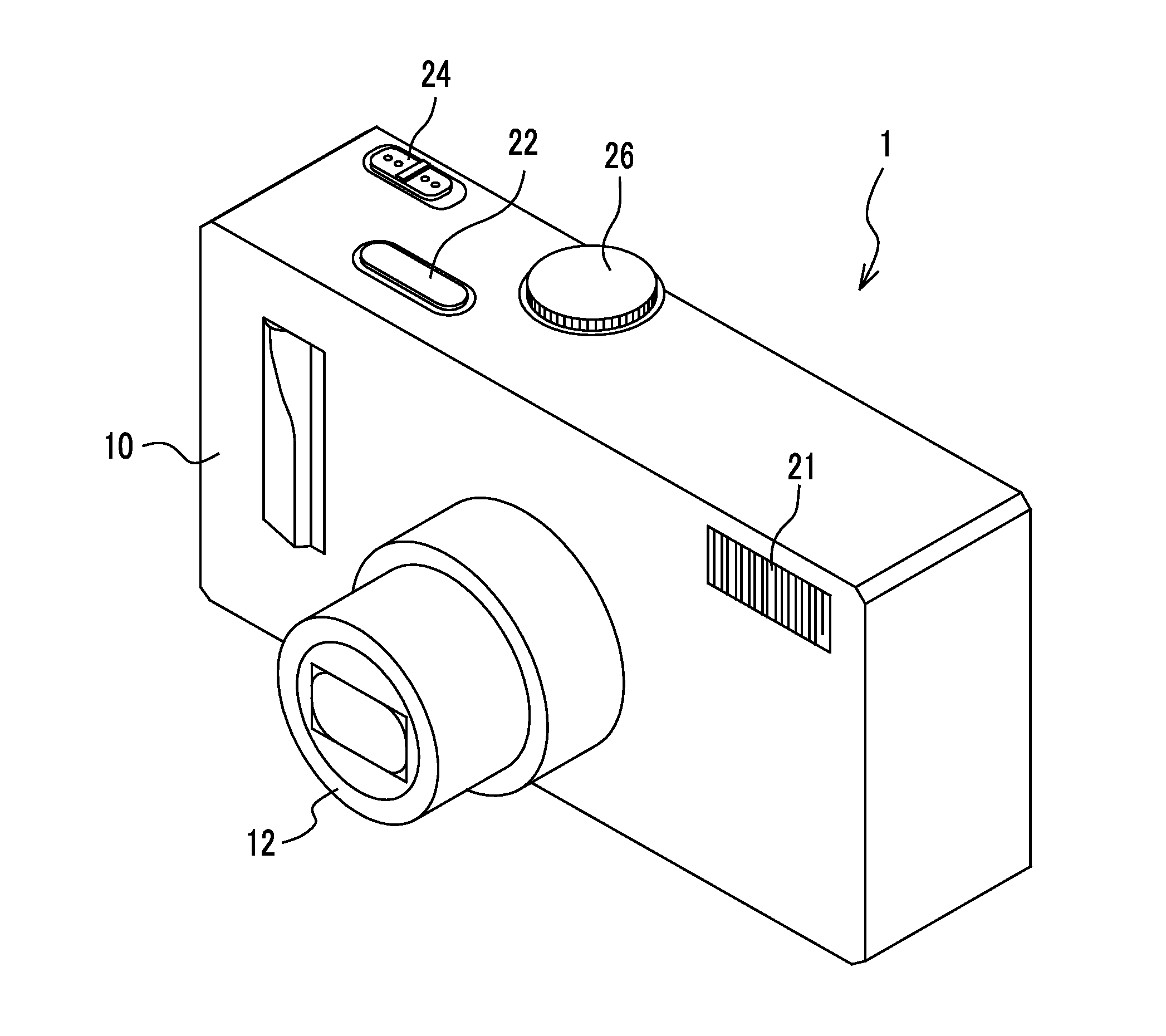
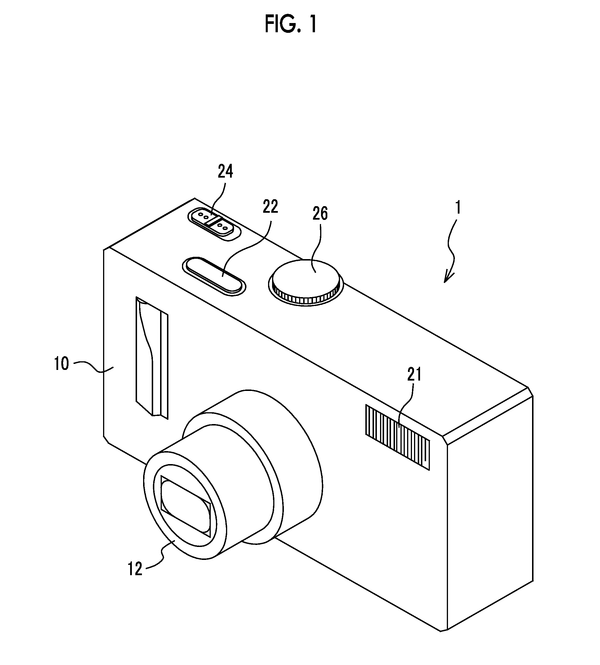
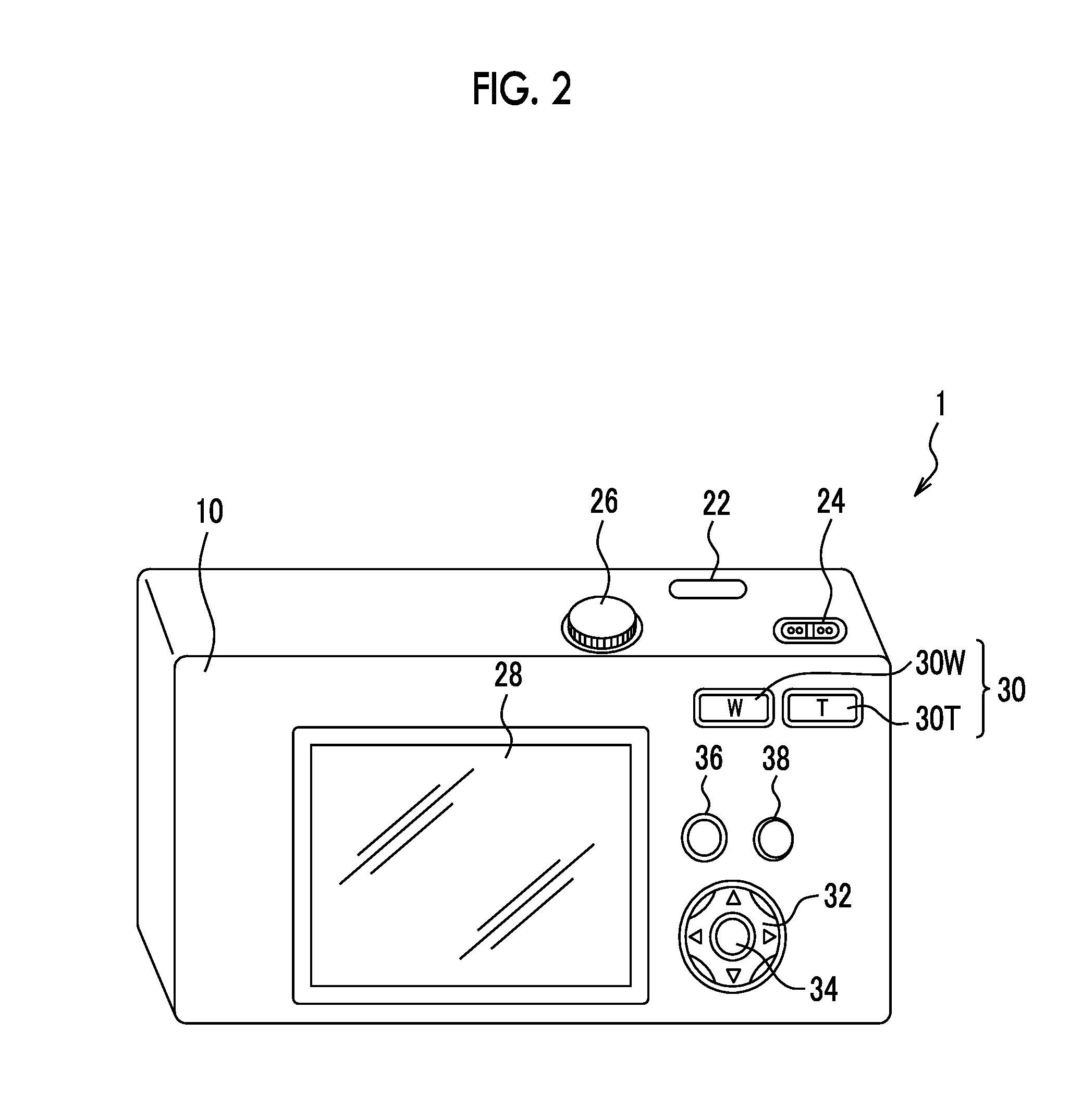
[0070]FIG. 1 is a perspective view illustrating an example of a single-eye stereoscopic imaging device 1, which is an imaging device according to a first embodiment of the present invention. FIG. 2 is a rear view illustrating an example of the single-eye stereoscopic imaging device 1. The single-eye stereoscopic imaging device 1 is a digital camera that receives light which has passed through a lens using an imaging element, converts the light into a digital signal, and records the digital signal on a recording medium.

[0071]A camera body 10 of the single-eye stereoscopic imaging device 1 has a horizontally-long square box shape. For example, a lens unit 12 and a flash lamp 21 are provided on the front surface of the camera body 10, as shown in FIG. 1. For example, a shutter button 22, a power / mode switch 24, and a mode dial 26 are provided on the upper surface of the camera body 10. As shown in FIG. 2, for example, a liquid crystal monitor ...

second embodiment

[0152]In the first embodiment of the present invention, the one-dimensional correction table for the main pixel and the one-dimensional correction table for the sub-pixel are stored. However, the one-dimensional correction table may be shared by the main pixel and the sub-pixel.

[0153]In a second embodiment of the present invention, the same one-dimensional correction table is used for the main pixel and the sub-pixel. Next, a single-eye stereoscopic imaging device 2 according to the second embodiment will be described. The imaging device has the same internal structure as the imaging device according to the first embodiment except for an SD correction unit. Therefore, the description of the same components is omitted and only the SD correction unit will be described. In addition, the operation of the imaging device is the same as that of the imaging device according to the first embodiment except for a shading correction method and only the shading correction method will be describe...

third embodiment

[0170]In a third embodiment of the present invention, similarly to the second embodiment, the same one-dimensional correction table is used for main pixels and the sub-pixels. Next, a single-eye stereoscopic imaging device 3 according to the third embodiment will be described. The imaging device has the same internal structure as the imaging device according to the first embodiment except for an SD correction unit. Therefore, the description of the same components is omitted and only the SD correction unit will be described. In addition, the operation of the imaging device is the same as that of the imaging device according to the first embodiment except for a shading correction method and only the shading correction method will be described. In the third embodiment, the same components as those in the first and second embodiments are denoted by the same reference numerals and the description thereof will not be repeated.

[0171][Internal Structure of Imaging Device]

[0172]FIG. 15 is a...


PUM


Abstract

Provided is a technique capable of correcting unique shading characteristics of a single-eye stereoscopic imaging device. A focal length is acquired. A one-dimensional correction table corresponding to the focal length is acquired from a plurality of stored one-dimensional correction tables. Shading correction is performed using the acquired one-dimensional correction table. An arbitrary pixel is selected from main pixels, a correction value corresponding to the position of the selected pixel is read from the acquired one-dimensional correction table for the main pixel, and shading correction is performed for the basis of the correction value and the value of the arbitrary pixel. This process is performed for all of the main pixels and the sub-pixels. A two-dimensional SD correction unit performs normal shading correction for the data subjected to the shading correction using a two-dimensional correction table.

Description

BACKGROUND OF THE INVENTION[0001]1. Field of the Invention[0002]The present invention relates to a single-eye stereoscopic imaging device, a correction method thereof, and a recording medium thereof, and more particularly, to a technique which forms object images passing through different regions of an imaging lens in the lateral direction on an imaging element to acquire an image for the left eye and an image for the right eye.[0003]2. Description of the Related Art[0004]JP2008-270937A discloses a technique which performs shading correction for at least one of an image for the right eye and an image for the left eye when the image for the right eye and the image for the left eye are acquired from individual imaging elements to generate a stereoscopic image.[0005]JP2007-279512A discloses a stereoscopic imaging element in which a microlens is provided on each photodiode forming one imaging element and the position of the microlens deviates from the position of the corresponding photo...

Claims


Application Information

Patent Timeline
IPC IPC(8): H04N13/00
CPCH04N13/0025G03B35/08H04N5/16H04N13/133H04N13/218H04N13/236H04N13/271H04N25/61
Inventor HASEGAWA, RYOHAYASHI, KENKICHITANAKA, SEIJI
Owner FUJIFILM CORP
Learn More