
Electrowetting optical element

a technology of optical elements and electrowetting, applied in the field of electrowetting optical elements, can solve the problems of destroying the electrowetting element, deteriorating pixel walls, and poor transmissibility of non-polar liquid, so as to improve structural integrity and switching behavior.

Active Publication Date: 2013-10-24
MIORTECH HLDG
View PDF3 Cites 13 Cited by
  • Summary
  • Abstract
  • Description
  • Claims
  • Application Information

AI Technical Summary

Benefits of technology

The invention aims to improve the structure and behavior of an electrowetting optical element. It seeks to overcome the problems and disadvantages of the prior art. Overall, the invention enhances the performance of the electrowetting optical element.

Problems solved by technology

The poor transmissibility of the non-polar liquid then forms an obstruction to light that penetrates the system.
Electrowetting elements according to the state of the art exhibit poor adhesion of the pixel wall to the hydrophobic surface, causing the pixel walls to deteriorate, thereby destroying the electrowetting element and it's surrounding electrowetting elements which are defined by the pixel walls.
This is due to the fact that the hydrophobic surface has a very low contact angle hysteresis and low surface tension which makes it extremely difficult to apply an uniform coating of photoresist from which the pixel walls are formed.
Furthermore the adhesion of the photoresist to the hydrophobic surface is very poor, thus resulting in poor adhesion and deterioration of the pixel walls.
This problem may already occur during manufacturing of the electrowetting elements, when pixel walls are created.
As a result, the yield of commercial manufacturing processes is lowered and in addition the technical life of electrowetting displays is shortened.
However the return to a hydrophobic state with minimal contact angle hysteresis is often not perfect causing imperfect spreading of the oil after switching to the unpowered state.
Such a method thus leads to problems with the opening and closing of the pixels during switching operation.

Method used


Image

  • Electrowetting optical element
  • Electrowetting optical element
  • Electrowetting optical element

Examples


Embodiment Construction

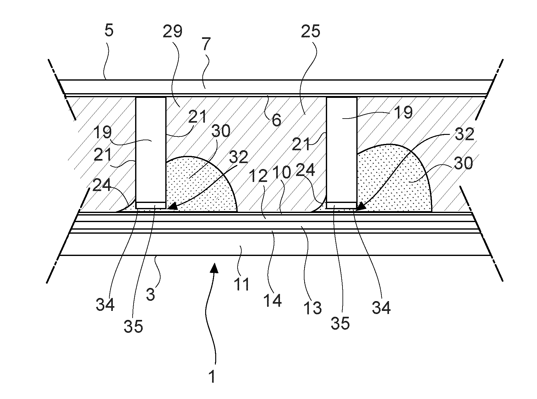
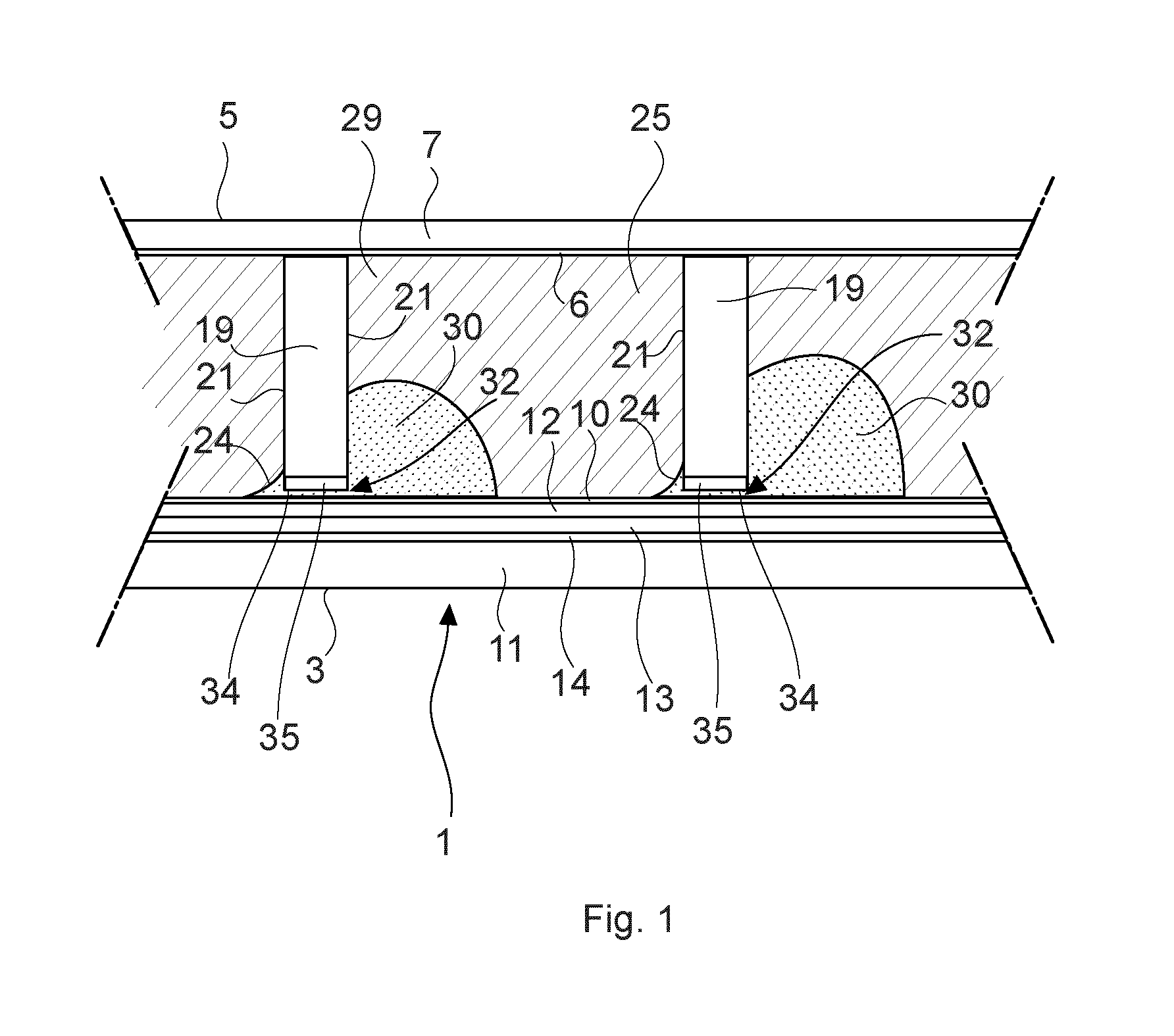
[0036]In FIG. 1, an electrowetting optical element or electrowetting element generally indicated with reference numeral 1, and situated between adjacent electrowetting elements, is illustrated. In the electrowetting element 1, a containment space 25 is present between a first electrode layer stack 3 and a second electrode layer stack 5. The first electrode layer stack 3 comprises a substrate 11, an insulating layer 12, a first electrode layer 13 and an optional reflective layer 14 that will be described below. The first electrode layer stack 3 is formed of an electrically conducting material such as indium tin oxide (ITO) and has a hydrophobic interface surface 10 forming the interface with the containment space 25. The hydrophobic interface surface 10 can be formed by a layer of a suitable fluoropolymer, such as CYTOPtm or AF1600tm.

[0037]The second electrode layer stack 5 comprises a superstrate 7 and a second electrode layer 6 supported by the superstrate 7. The second electrode l...


PUM

PropertyMeasurementUnit
hydrophobicaaaaaaaaaa
hydrophobicityaaaaaaaaaa
surface tension forcesaaaaaaaaaa

Abstract

An electrowetting optical element comprising a first electrode layer stack and a second electrode layer stack, and a containment space formed between said first electrode layer stack and said second electrode layer stack, one or more pixel walls fixedly mounted on said second interface surface and extending between said first and second electrode stacks, for defining sides of said containment space. Said containment space at least contains a polar liquid and a non-polar liquid, the polar and non-polar liquids being immiscible with each other. Said hydrophobic interface surface has a higher hydrophobicity than the second interface surface. The electrowetting element is arranged for enabling powering of said first and second electrode layers for rearranging said polar liquid relative to said non-polar liquid. An end face of said one or more pixel walls opposite said first electrode layer stack faces said hydrophobic interface surface in a loose manner.

Description

FIELD OF THE INVENTION[0001]The present invention relates to an electrowetting optical element, a display comprising electrowetting optical elements and a method of manufacturing an electrowetting optical element.BACKGROUND[0002]Electrowetting technology is based on modification of an energy balance between on one hand surface tension forces of liquids and wetting properties of a solid surface, and on the other hand electrostatic forces induced by an applied voltage over a capacitor arrangement comprising said boundary layer.[0003]An electrowetting optical element or cell, further referred to as electrowetting element, according to the state of the art may from bottom to top be comprised of respectively a first electrode layer stack comprising a substrate, a first electrode layer, an electrically insulating hydrophobic layer or an insulating layer having a hydrophobic surface on a side opposite to the first electrode layer, for interfacing to a polar liquid and a non-polar liquid im...

Claims


Application Information

Patent Timeline
Patent Type & Authority Applications(United States)
IPC IPC(8): G02B26/00
CPCG02B26/005Y10T29/49204G02B26/02
Inventor FEIL, HERMANUS
Owner MIORTECH HLDG
Learn More