Monitoring of underwater mooring lines

a technology for underwater mooring and monitoring, which is applied in the direction of mooring equipment, vessel construction, transmission, etc., can solve the problems of instrumented load shackles, connectors and cables exposed, and mooring lines used in these situations are generally of a significant length,

Inactive Publication Date: 2013-10-24
INTERMOOR +1
View PDF44 Cites 18 Cited by
  • Summary
  • Abstract
  • Description
  • Claims
  • Application Information

AI Technical Summary

Benefits of technology

[0011]It is an object of the present invention to address the problems cited above, and provide an improved mooring line monitor for monitoring at least one operational condition of an underwater mooring line.

Problems solved by technology

The mooring lines used in these situations are generally of a significant length, and may need to bear loads of many hundreds, or even thousands, of tonnes.
A number of problems have been noted with the use of instrumented load shackles.
The connectors and cables are exposed and vulnerable to handling damage either when the mooring line is set in place or at a later time when work is done around the mooring line.
Cables running down a mooring line tend to fail prematurely.
It is hard to restrain a cable to the mooring line without the cable being too loose, which can cause a loop to form in the cable.
Slack in the cable results in fatigue where the cable breaks the surface, either due to surface currents or waves.
On the other hand, if the cable is too tight, the cable will either snap or be pulled out from cable connectors.
There is typically no easy way for a cable to leave the mooring line and join the vessel or platform.
The cable either has to have long lengths unsupported in the splash zone, and often a cable may have to run over sharp edges or be routed in fare leads.
The installation and recovery of a mooring line monitoring system that uses cables is a long and tricky job, and this is compounded when there is bad weather or when it is necessary to work on the back of an anchor handler deck.
Over the life of the mooring installation, the end link of the chain may move away from the centre of the spool which can lead to very inaccurate results.
An estimate of mooring line tension may be gained from calculations when the mooring line forms a known catenary shape, but this is typically only possible on permanent installations.
The catenary shape of the mooring line is also likely to change over its life due to creep or decay.
In addition, large mooring systems require life spans of up to 30 years in a permanent position and, therefore, any connectors must withstand the harsh offshore environment.

Method used


Image

  • Monitoring of underwater mooring lines
  • Monitoring of underwater mooring lines
  • Monitoring of underwater mooring lines

Examples


Embodiment Construction

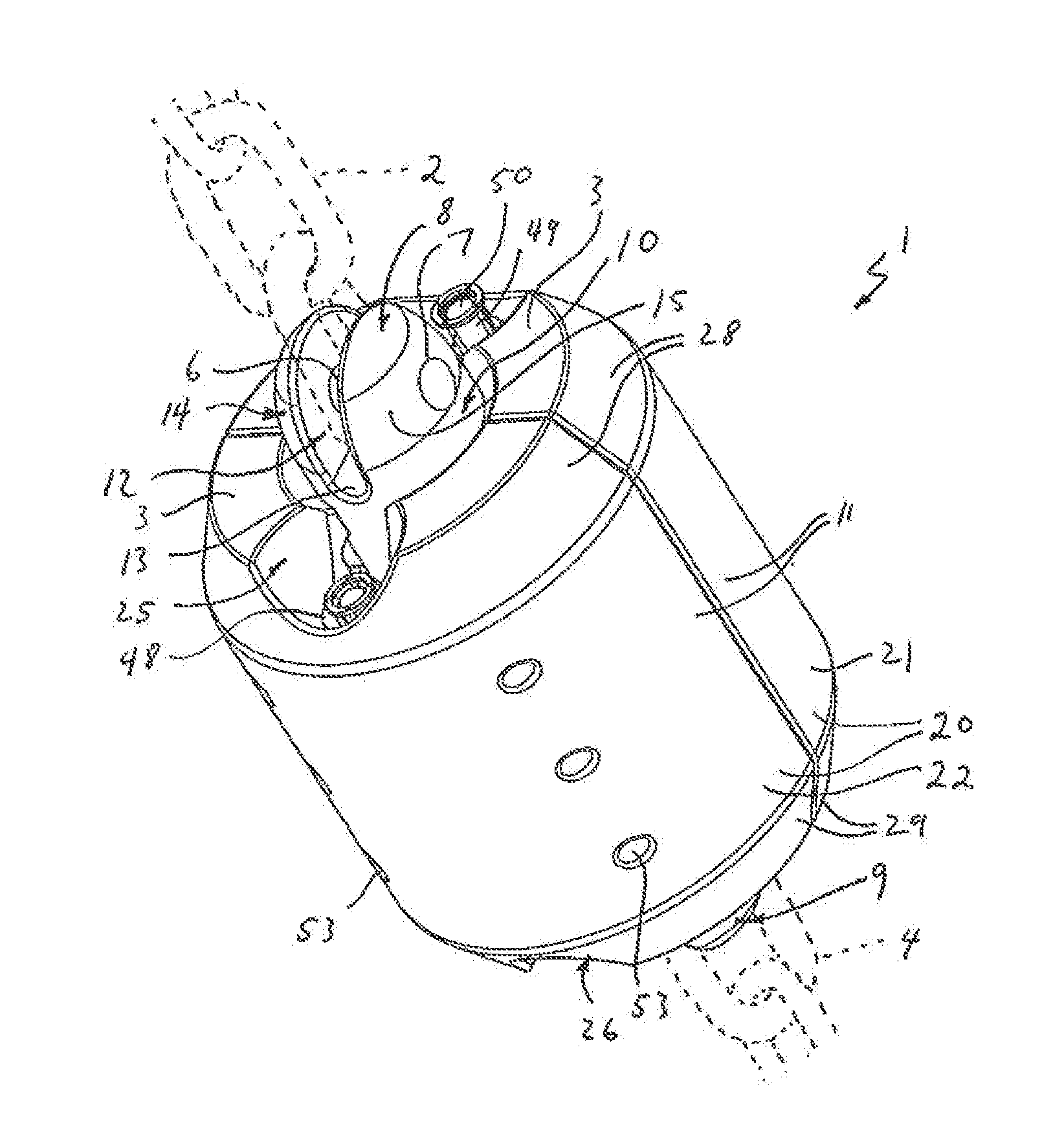
[0037]FIG. 1 shows a mooring line monitor 1 of a preferred embodiment of the invention for use in long term mooring applications. In use, the mooring line monitor 1 will form a joining link within a mooring line below the water line, for example when mooring floating production systems or mooring of mobile offshore units. The monitor will typically be installed at a natural join within a mooring line. Although FIG. 1 shows in dashed outline the ends of two lengths of steel chain links, 2, 4, either or both ends of the mooring line monitor 1 may equally well be connected to other types of mooring line, for example fiber tether. The mooring line monitor may therefore be used either to link two lengths of similar lines, or be used to connect two dissimilar mooring lines, for example chain link and steel rope.

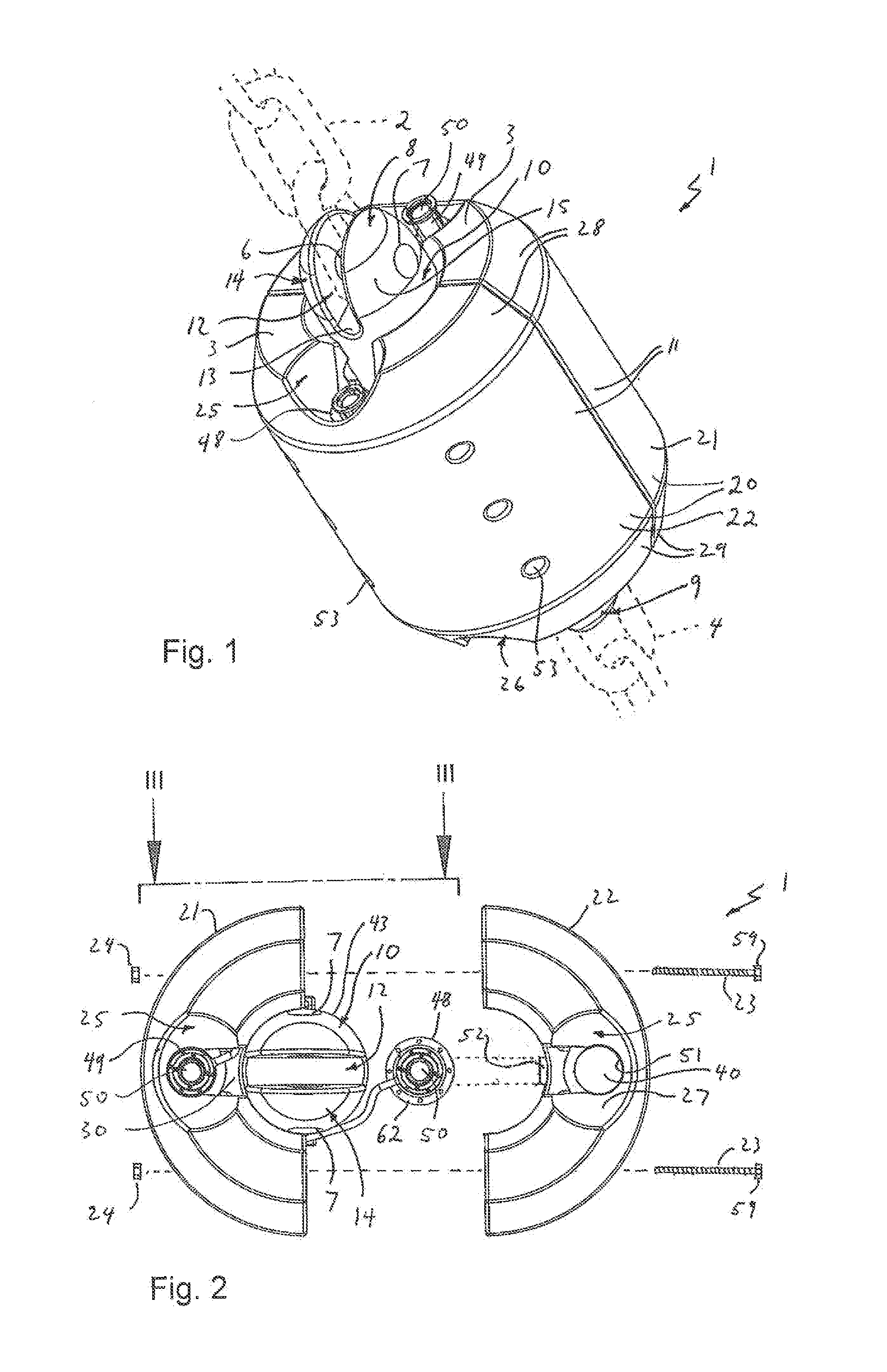
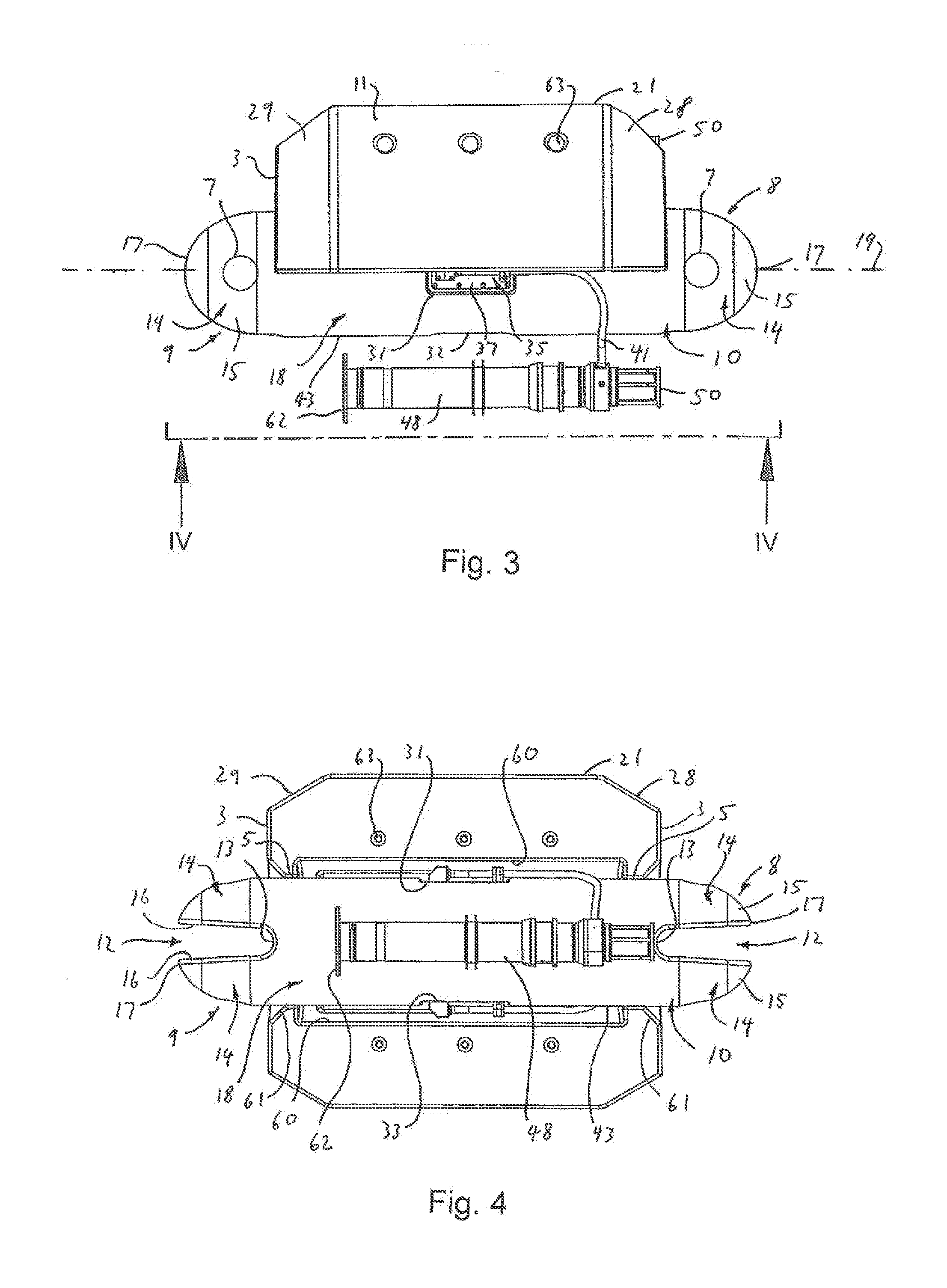
[0038]The mooring line monitor 1 comprises an elongate main body 10 and two pin assemblies one of which 6 is visible in the drawings. Each pin assembly is removable from the main b...


PUM

PropertyMeasurementUnit
diameteraaaaaaaaaa
diameteraaaaaaaaaa
widthaaaaaaaaaa

Abstract

In some aspects of the inventive subject matter, there is provided a monitor for monitoring at least one operational condition of an underwater mooring line, the monitor comprising an elongate main body, a protective shroud, at least one operational condition sensor for monitoring the, or each, operational condition, at least one acoustic transmitter, and (in some instances) a source of electrical power for powering the operation of the sensor and transmitter. The main body has at first and second ends respectively first and second mooring line connections (each configured for connection to a respective mooring line) and an intermediate portion. In use, the intermediate section is under tension between the first and second ends when the mooring line is under load. The, or each, operational condition sensor is attached to the intermediate section, the sensor having a signal output for providing a signal regarding the sensed operational condition.

Description

BACKGROUND[0001]a. Field of the Invention[0002]The present invention relates to the monitoring of underwater mooring lines, for example heavy duty anchoring chains or steel rope lines. In particular, this invention relates to monitoring the tension and / or the inclination in underwater mooring lines, for example as used in the offshore oil and gas industry.[0003]b. Related Art[0004]Mooring components may be used in several applications, for example in the long-term mooring of floating production systems or mooring of mobile offshore units.[0005]The mooring lines used in these situations are generally of a significant length, and may need to bear loads of many hundreds, or even thousands, of tonnes. The mooring lines may be formed from chain links or fiber material, for example steel rope.[0006]There is often the need to measure direct in-line tension and inclination of a mooring line. One known way of doing this is to use an instrumented load shackle connected to the mooring line. A ...

Claims


Application Information

Patent Timeline
Patent Type & Authority Applications(United States)
IPC IPC(8): H04B13/02B63B21/20G01L1/00
CPCB63B21/20B63B2021/008B63B2021/009B63B2021/203G01L5/101G01L11/025H04B11/00
Inventor PRENTICE, WILLIAM MARKFOWLER, JAMES STUART
Owner INTERMOOR
Why Eureka
Try Eureka