Tube Reactor for Chemical Vapor Deposition

a technology tube reactor, which is applied in the direction of chemical vapor deposition coating, coating, metal material coating process, etc., can solve the problems of cvd system of furnace, increase of manufacturing cost and manufacturing error, and roundness of process tubes, so as to achieve greater throughput and energy. the effect of greater amoun

Inactive Publication Date: 2013-10-24
BLUESTONE TECH CAYMAN
View PDF0 Cites 0 Cited by
  • Summary
  • Abstract
  • Description
  • Claims
  • Application Information

AI Technical Summary

Benefits of technology

[0006]Embodiments of the present invention address the above-identified needs by providing new apparatus for film deposition by CVD, as well as methods for their use. Advantageously, apparatus in accordance with aspects of the invention provide substantially greater throughput than conventional single-tube CVD reactors while not requiring that process tube diameters be substantially increased. At the same time, through the use of compact designs and the use of single heating sources, apparatus in accordance with aspects of the invention do not create a footprint that is substantially larger than a conventional single-tube CVD reactor nor do they consume a substantially greater amount of energy per run.

Problems solved by technology

Nevertheless, despite their widespread use, furnace CVD systems may suffer from several disadvantages.
However, both manufacturing costs and manufacturing errors increase when increasing process tube size.
In addition, the roundness of the process tube may be compromised with greater process tube diameter, which may make it problematic to achieve a reliable vacuum seal with metal end-ports.
Finally, the greater the size of the process tube, the more difficult it becomes to manage processing conditions therein.

Method used


Image

  • Tube Reactor for Chemical Vapor Deposition
  • Tube Reactor for Chemical Vapor Deposition
  • Tube Reactor for Chemical Vapor Deposition

Examples


Embodiment Construction

[0017]The present invention will be described with reference to illustrative embodiments. For this reason, numerous modifications can be made to these embodiments and the results will still come within the scope of the invention. No limitations with respect to the specific embodiments described herein are intended or should be inferred.

[0018]The term “film deposition” as used herein is intended to encompass both what is commonly called film deposition and film growth. Thus, the term “film deposition” would include the forming of films that differ in composition and / or crystallinity from the respective substrates on which they are deposited, as well as the forming of films that substantially match the composition and crystallinity of the respective substrates on which they are deposited.

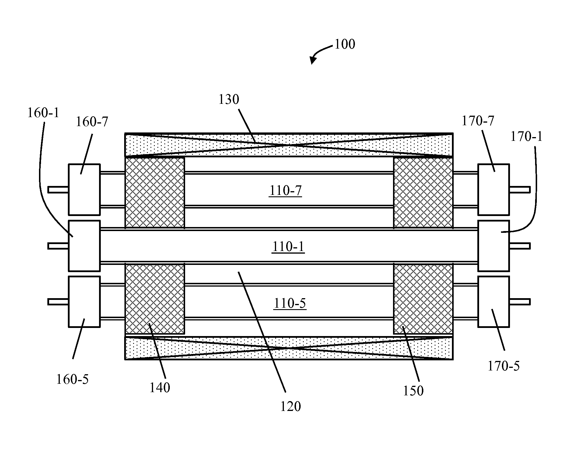
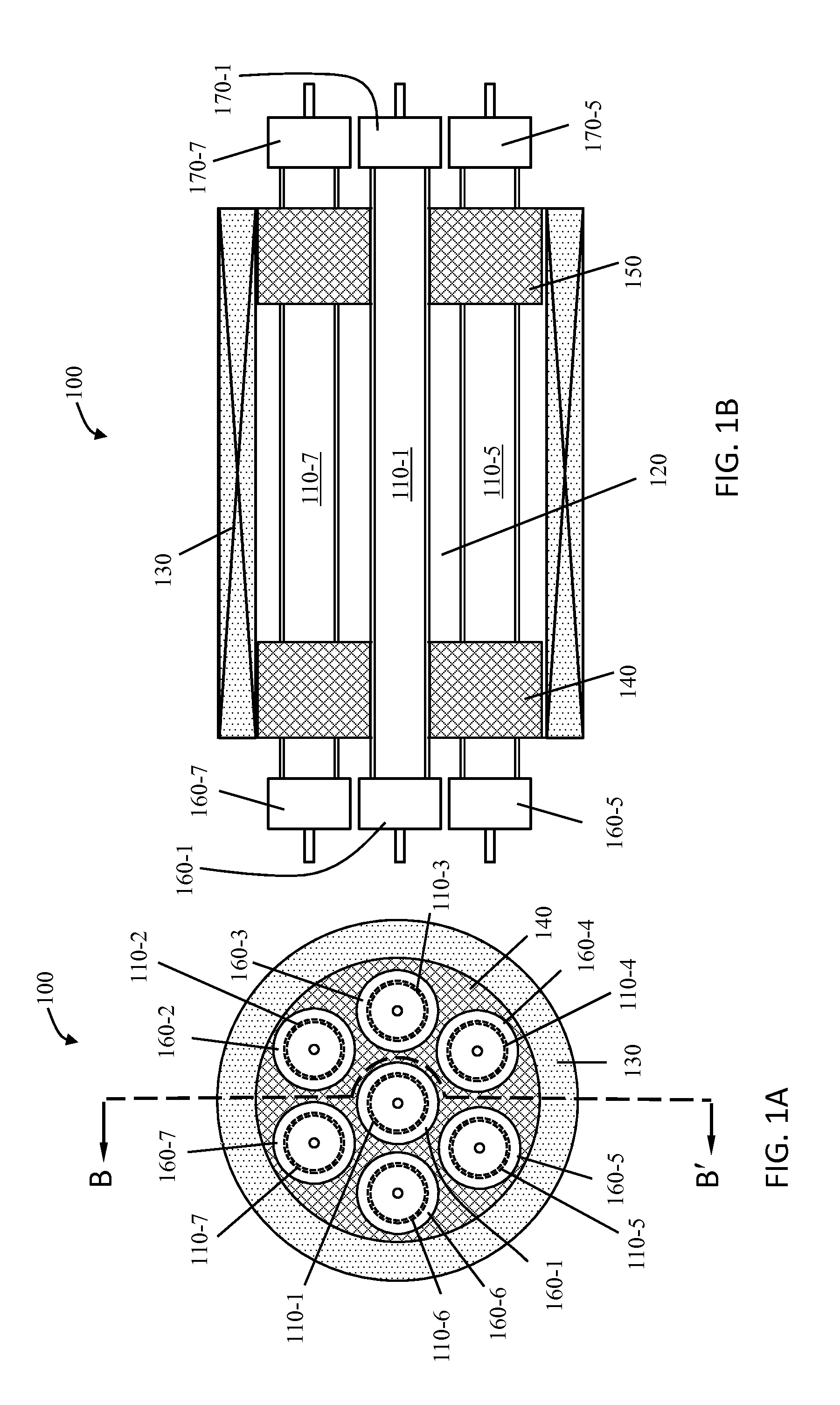
[0019]FIGS. 1A and 1B show at least a portion of a CVD tube reactor 100 in accordance with an illustrative embodiment of the invention. More particularly, FIG. 1A shows a side elevational view of the ...


PUM

PropertyMeasurementUnit
temperaturesaaaaaaaaaa
energyaaaaaaaaaa
magnetic fieldaaaaaaaaaa

Abstract

An apparatus for performing film deposition, comprises an energy source, a plurality of process tubes, and a gas manifold. The energy source is adapted to direct energy into a cylindrical space. The plurality of process tubes, in turn, pass through this cylindrical space. To perform the film deposition, the gas manifold is operative to introduce a respective gas flow into each of the plurality of process tubes.

Description

FIELD OF THE INVENTION[0001]The present invention relates generally to apparatus and methods for chemical processing, and, more particularly, to tube-based reactors for chemical vapor deposition.BACKGROUND OF THE INVENTION[0002]Chemical vapor deposition (CVD) is widely used in the semiconductor industry as well as other industries to form non-volatile solid-films on a substrate. In a typical CVD process, a given composition and flow of reactant gases are introduced into a reaction space where they are adsorbed onto a substrate. There, the reactants undergo migration and film-forming chemical reactions. The reaction by-products are then desorbed from the substrate and removed from the reaction space.[0003]Furnace CVD systems (horizontal or vertical) are commonly utilized for CVD. In a typical furnace CVD system, the chemical reactants are flowed through a cylindrical quartz or alumina process tube that houses the substrate. The process tube, in turn, is surrounded by a heating furnac...

Claims


Application Information

Patent Timeline
Patent Type & Authority Applications(United States)
IPC IPC(8): C23C16/455
CPCC23C16/455C23C16/52
Inventor LI, XUESONGLIN, YU-MINGSUNG, CHUN-YUNG
Owner BLUESTONE TECH CAYMAN
Why Eureka
Try Eureka