System and Method for Identifying Impending Hydraulic Pump Failure

Active Publication Date: 2013-10-31
CATERPILLAR INC
View PDF5 Cites 55 Cited by
  • Summary
  • Abstract
  • Description
  • Claims
  • Application Information

AI Technical Summary

Benefits of technology

[0008]In accordance with one aspect of the disclosure, a method of determining impending hydraulic pump failure in a multiple pump hydraulic system is therefore disclosed. The method may include measuring volumetric deficiency of the hydraulic system, determining that one of the multiple pumps in the system is approaching failure when the volumetric deficiency is decreasing at a rate greater than a predetermined threshold, measuring pump displacement

Problems solved by technology

While effective, and used pervasively throughout the industrial world, it can be seen that such hydraulic systems are heavily dependent on proper operation of the engine and pumps.
With specific reference to the pumps, if any one of the pumps were to fail, the pressure within the system would also fail and the ability of the machine to perform its designated tasks or work function would also fail.
In a construction or mining operation this is simply unacceptable.
Any amount of downtime, i.e. time during which the machine is not operational, is lost workflow to the owner of the machine, and thus lost profit.
The pump failure can manifest itself in any number of ways including catastrophic or explosive or more prolonged or incremental.
With the former, of course this is hazardous to the operator and those around the machine and immediately results in a non-operational machine.
As such machines are often operated in very remote locales, the downtime is also often of a significant duration.
In even worse situations, the machine has to be transported to a re

Method used


Image

  • System and Method for Identifying Impending Hydraulic Pump Failure
  • System and Method for Identifying Impending Hydraulic Pump Failure
  • System and Method for Identifying Impending Hydraulic Pump Failure

Examples


Embodiment Construction

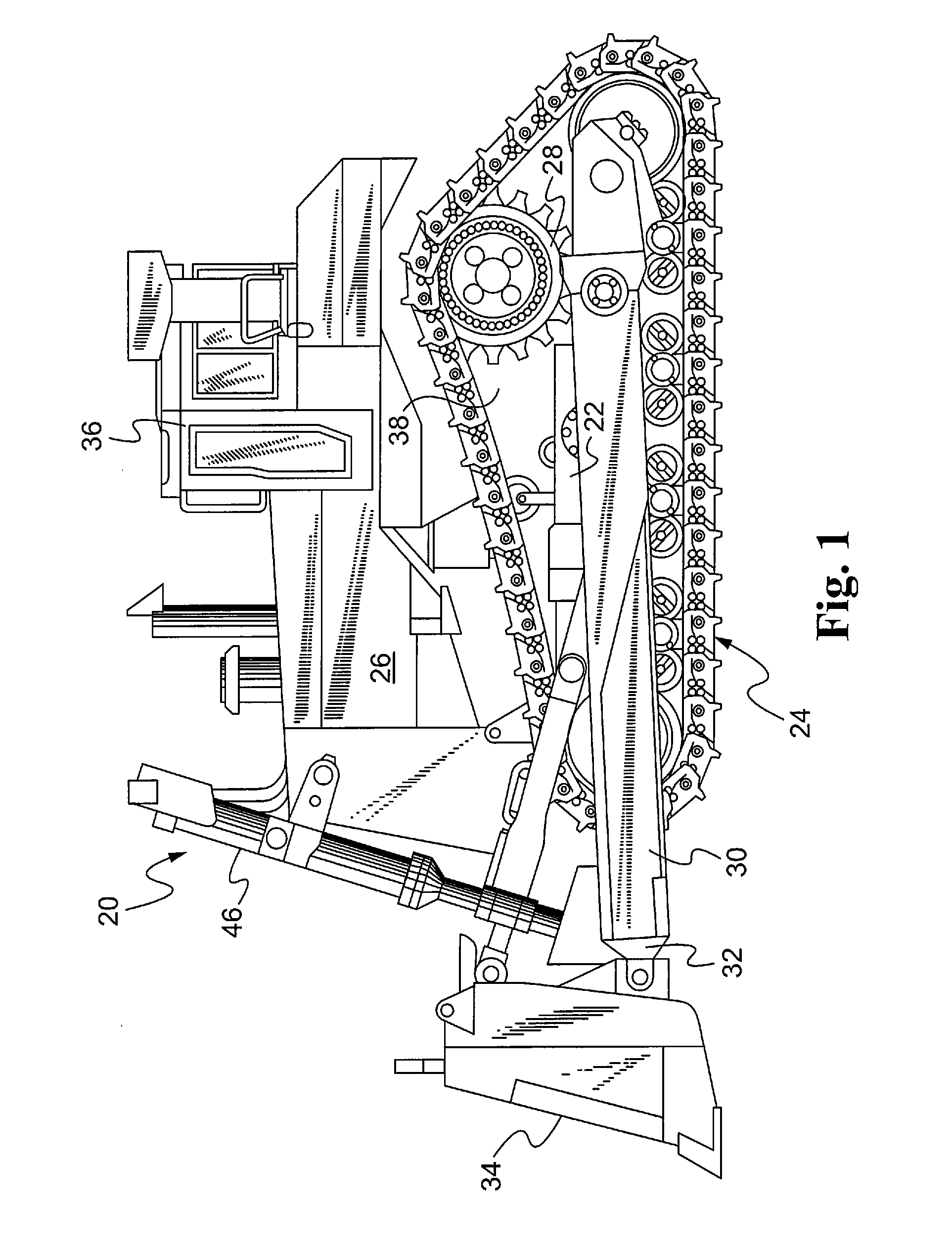
[0016]Referring now to FIG. 1, a machine constructed in accordance with the teachings of the disclosure is generally referred to be reference numeral 20. While machine 20 depicted in FIG. 1 is that of a track type tractor, it is to be understood that the teachings of this disclosure can be used on any machine using hydraulics including, but not limited, to various construction, agricultural, mining, and other earth-moving operations. Such machines may include, but not be limited to, loaders, excavators, trucks, pipe layers, graders, harvesters, lift trucks, paving machines, and the like, all of which may be wheeled or driven by tracks.

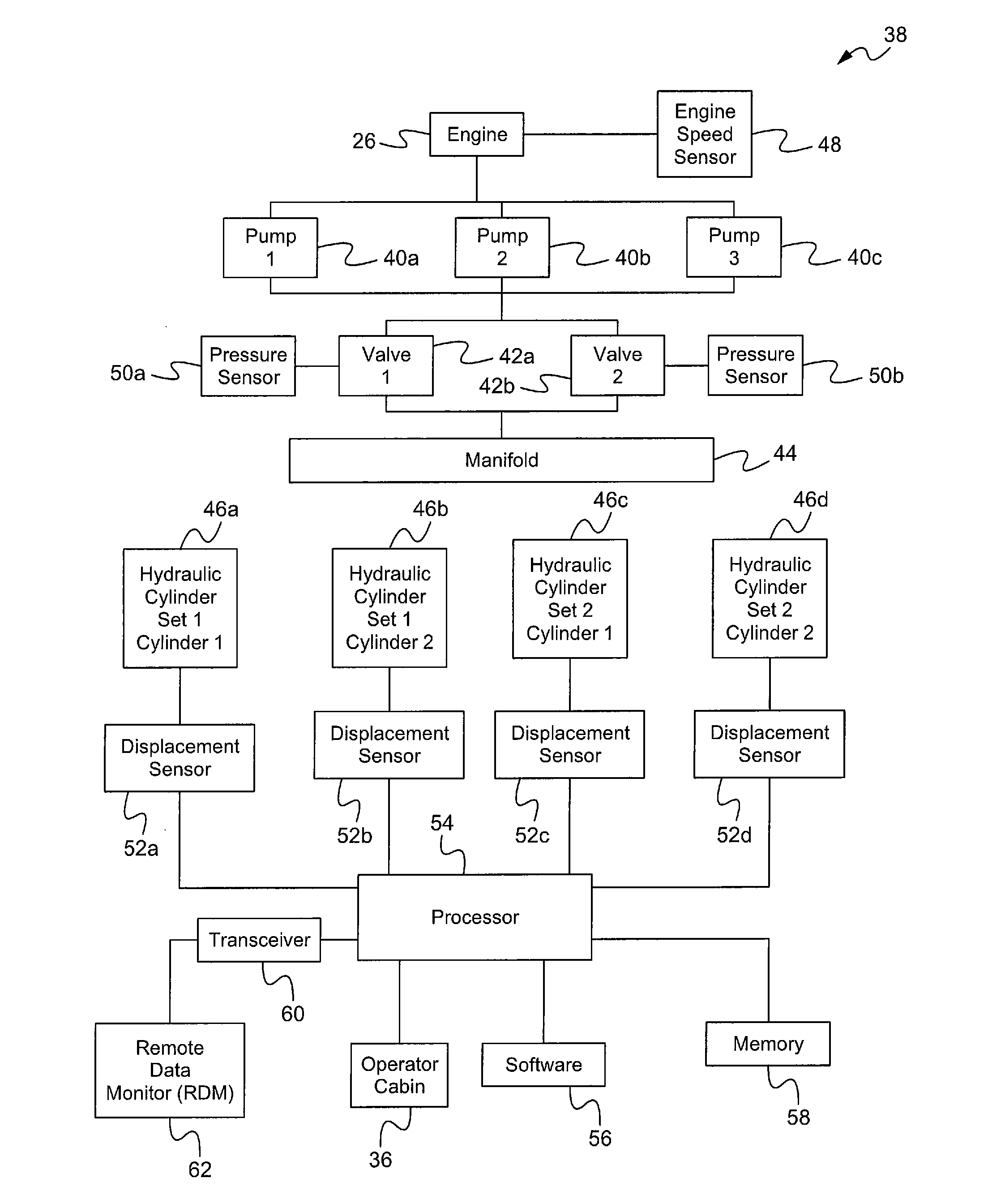
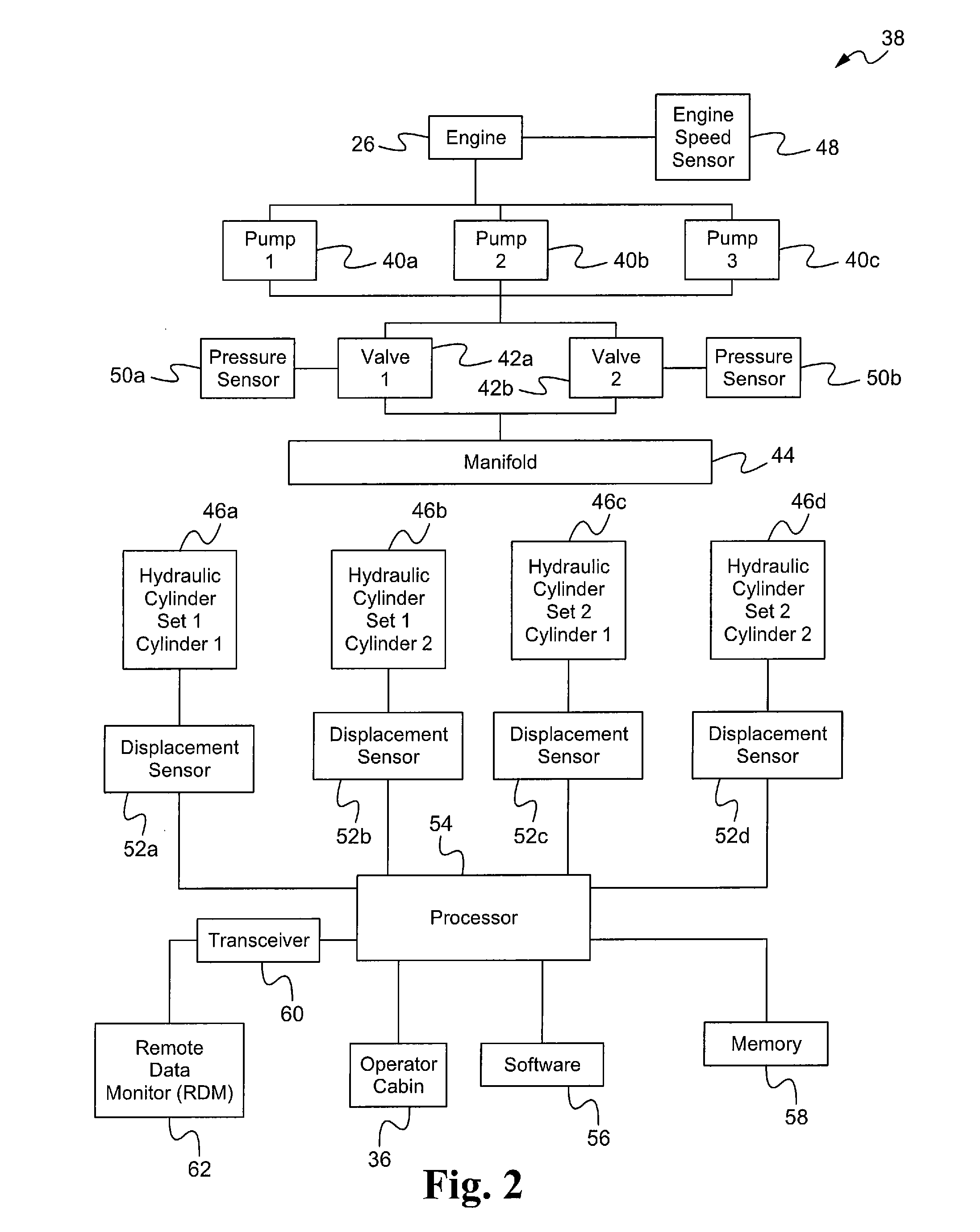
[0017]As shown therein, the machine 20 may include a chassis 22 which is supported for motion by way of wheels, or in the case of FIG. 1, a continuous track 24. Chassis 22 also supports an engine 26 connected by way of drivetrain 28 to the aforementioned wheels or track 24. Extending from the chassis 22 may be one or more work arms 30 to a distal end 3...


PUM


Abstract

A system and method for predicting impending pump failure in a hydraulic system is disclosed. The system measures and compares the running and moving volumetric deficiencies of the hydraulic system as a whole and if they are not within range of each other by a predetermined threshold, the system determines that at least one of the pumps in the system is about to fail. If such a determination is made by the system, the pump displacement is at standby of each pump is then calculated and the pump with the greatest displacement at standby is determined to be the pump approaching failure. Once the pump approaching failure is identified, a signal is generated to apprise the operator or other entity to enable corrective action to be taken.

Description

TECHNICAL FIELD[0001]The present disclosure generally relates to hydraulic systems and, more particularly, relates to diagnostic monitoring systems for identifying impending pump failures in hydraulic systems.BACKGROUND[0002]Hydraulic systems are widely used to perform useful work. Common applications are found on earth-moving and mining machines which use hydraulic systems to move various work tools. For example, on a wheeled or track-type loader, the hydraulic system may be used to raise and lower the arms of the loader as well as tilt a bucket or other work tool attached to the end of the movable arms. In such a system, an engine, typically a diesel engine, is mounted on a chassis and connected by way of a drivetrain to a plurality of wheels or continuous tracks to provide locomotion to the machine. The engine also is used to drive one or more hydraulic pumps to maintain pressure within the hydraulic system of the machine. The one or more pumps are in turn connected to one or mor...

Claims


Application Information

Patent Timeline
IPC IPC(8): F15B13/00G01N33/00
CPCF04B49/106F04B51/00F15B19/005F15B2211/20546F15B2211/20576E02F9/267F15B2211/633F15B2211/6336F15B2211/6652F15B2211/855E02F9/2292F15B2211/6306
Inventor HAGUE, M. EVAN
Owner CATERPILLAR INC
Why Eureka
Try Eureka