Air-conditioning apparatus

a technology of air-conditioning apparatus and compressor, which is applied in the direction of compressors with reversible cycles, heating and refrigeration combinations, refrigeration machines, etc., can solve the problems of limiting the discharge temperature and increasing the discharge temperature of the compressor, and achieve stable operation of the compressor and reduce the discharge temperatur

Active Publication Date: 2013-10-31
MITSUBISHI ELECTRIC CORP
View PDF5 Cites 19 Cited by
  • Summary
  • Abstract
  • Description
  • Claims
  • Application Information

AI Technical Summary

Benefits of technology

[0011]The air-conditioning apparatus according to the present invention injects the refrigerant into the compression chamber from the opening via the injection pipe so as to reduce the discharge temperature of the compressor, thereby allowing for the stable operation of the compressor.

Problems solved by technology

However, the density of the R32 refrigerant at the suction side of a compressor is smaller than that of the R410A refrigerant, thus causing the discharge temperature of the compressor to increase.
However, such a low-pressure-shell-type compressor is different from a high-pressure-shell-type compressor in that, since a liquid refrigerant is separated at the oil reservoir when the refrigerant is to be suctioned into the compressor, there is a limit to reducing the discharge temperature even if the refrigerant to be suctioned is moistened.

Method used


Image

  • Air-conditioning apparatus
  • Air-conditioning apparatus
  • Air-conditioning apparatus

Examples


embodiment 1

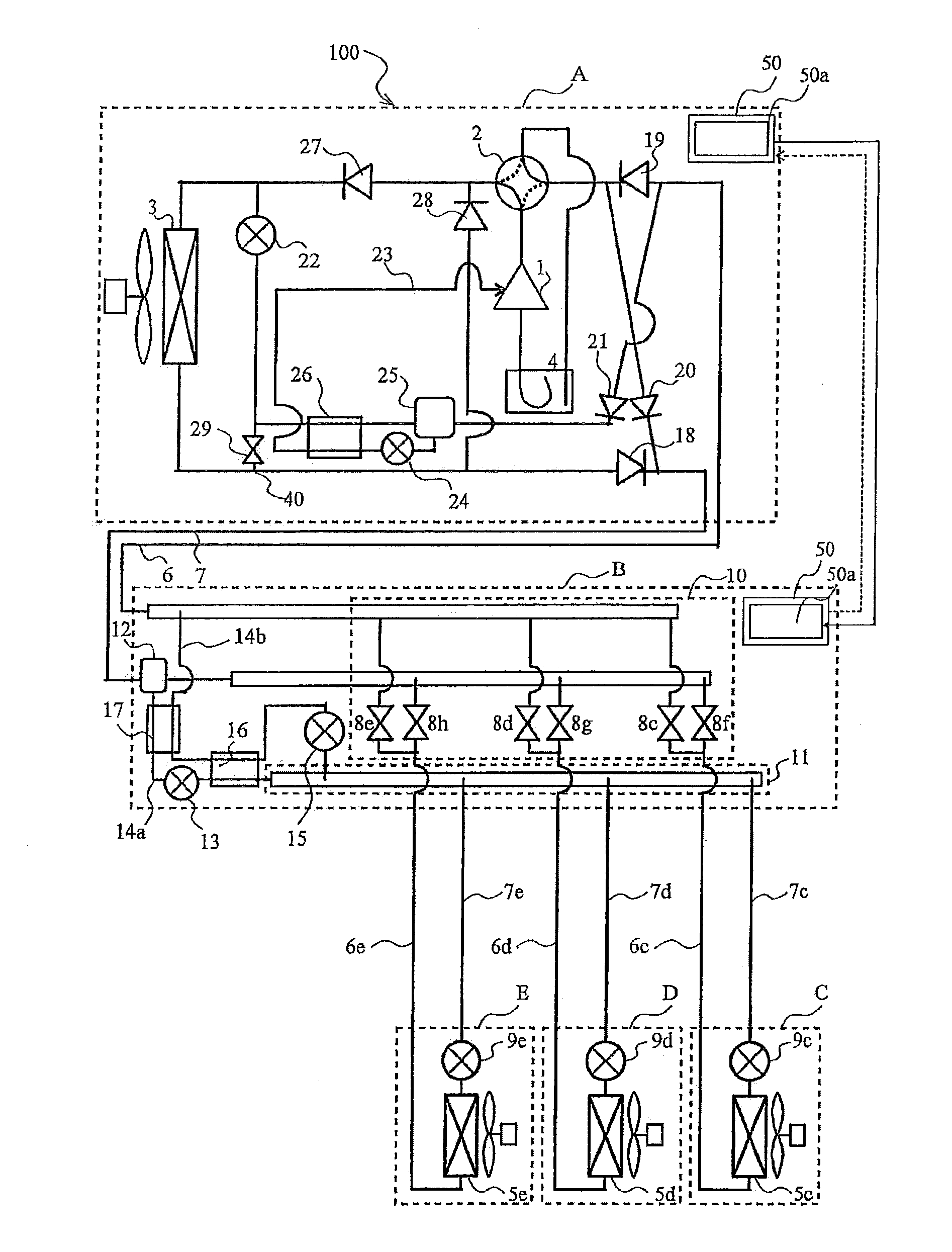
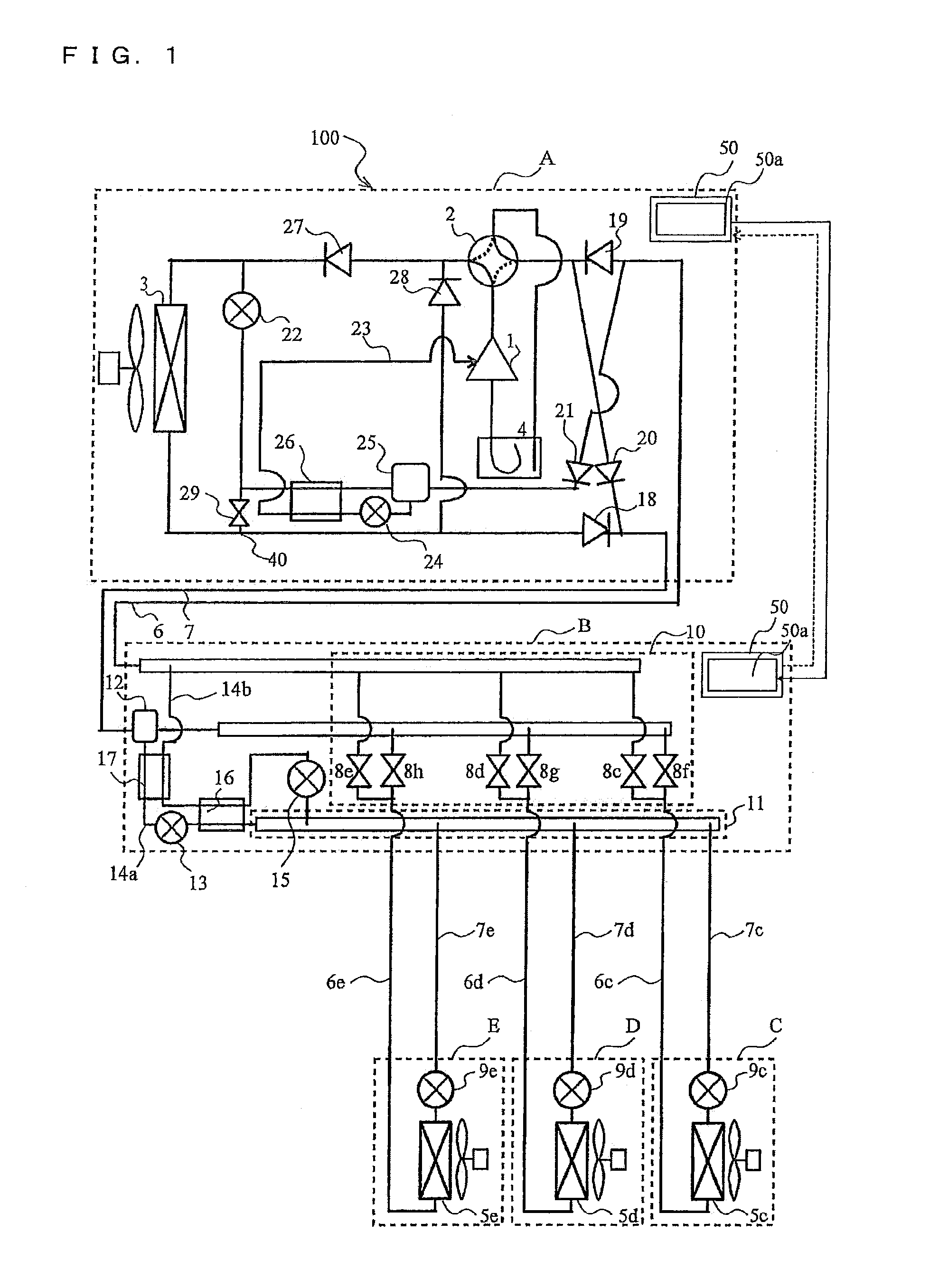
[0027]FIG. 1 is a refrigerant circuit diagram illustrating an example of a refrigerant circuit configuration of an air-conditioning apparatus 100 according to Embodiment 1. The refrigerant circuit configuration of the air-conditioning apparatus 100 will be described with reference to FIG. 1. The air-conditioning apparatus 100 according to Embodiment 1 has a function of reducing the temperature of a refrigerant to be discharged from a compressor so as to reduce deterioration of the refrigerant and refrigerating machine oil and fatigue in a seal material, etc. of the compressor.

[0028]Furthermore, the air-conditioning apparatus 100 is capable of executing a cooling only operation mode in which indoor units only perform a cooling operation, a heating only operation mode in which the indoor units only perform a heating operation, and a cooling and heating mixed operation mode in which the indoor units perform the cooling operation and the heating operation in a mixed fashion. The cooling...

embodiment 2

[0139]FIG. 12 is a refrigerant circuit diagram illustrating an example of a refrigerant circuit configuration of an air-conditioning apparatus 200 according to Embodiment 2. In Embodiment 2, sections that are the same as those in Embodiment 1 are given the same reference numerals or characters, and the following description will mainly be directed to different points from Embodiment 1. Similar to Embodiment 1, the first branch section 40 may be positioned in front of or behind the check valve 18 so long as the first branch section 40 is disposed in the pipe extending from the heat-source-side heat exchanger 3 to the second connection pipe 7. The air-conditioning apparatus 200 according to Embodiment 2 differs from the air-conditioning apparatus 100 according to Embodiment 1 in the extracting section of the injection pipe 23 extending out from the gas-liquid separator 25.

[0140]Specifically, in the air-conditioning apparatus 100 according Embodiment 1, when the injection is to be perf...

embodiment 3

[0142]FIG. 13 is a refrigerant circuit diagram illustrating an example of a refrigerant circuit configuration of an air-conditioning apparatus 210 according to Embodiment 3. In Embodiment 3, sections that are the same as those in Embodiment 1 are given the same reference numerals or characters, and the following description will mainly be directed to different points from Embodiment 1.

[0143]In the air-conditioning apparatus 210 according to Embodiment 3, the mainstream refrigerant travels through the gas-liquid separator 25 and the third heat exchanger 26 during cooling. In detail, a check valve 18-1 and a check valve 18-2 are connected in series in an area corresponding to the check valve 18 in Embodiment 1, and the gas-liquid separator 25, the third heat exchanger 26, the third flow control device 22, and the injection pipe 23 are connected to a pipe extending between the two check valves. Furthermore, in the inflow-side pipe extending into the gas-liquid separator 25, the check v...


PUM


Abstract

An air-conditioning apparatus uses R32, a refrigerant mixture containing R32 and HFO1234yf in which R32 has a mass percentage of 40% or higher, or a refrigerant mixture containing R32 and HFO1234ze in which R32 has a mass percentage of 15% or higher, as a heat-source refrigerant. The air-conditioning apparatus includes a low-pressure shell-structure compressor, a first flow switching valve, a heat-source-side heat exchanger, first flow control devices, and plural use-side heat exchangers connected by refrigerant pipes, forming a refrigeration cycle. The compressor includes a compression chamber within a sealed container including an opening extending between inside and outside of the sealed container. The air-conditioning apparatus can perform only a heating at the use-side heat exchangers, only a cooling at the use-side heat exchangers, and a mixed cooling and heating in a mixed fashion at the use-side heat exchangers.

Description

TECHNICAL FIELD[0001]The present invention relates to air-conditioning apparatuses, particularly, to an improved air-conditioning apparatus that reduces the temperature of a refrigerant to be discharged from a compressor.BACKGROUND ART[0002]In view of global environmental protection in recent years, there have been discussions with regard to switching refrigerants used for air conditioning from currently-used refrigerants with a high global warming potential (GWP), such as an R410A refrigerant, an R407c refrigerant, and an R134a refrigerant, to refrigerants with a low GWP, such as a carbon-dioxide refrigerant, an ammonia refrigerant, a hydrocarbon-based refrigerant, an HFO-based refrigerant, and an R32 refrigerant. Among these low-GWP refrigerants, an R32 refrigerant has an evaporating pressure and a condensing pressure that are substantially the same as those of an R410A refrigerant, and the refrigeration capacity per unit volume is greater than that of the R410A refrigerant, thus ...

Claims


Application Information

Patent Timeline
Patent Type & Authority Applications(United States)
IPC IPC(8): F25B29/00
CPCF25B29/003F25B9/006F25B13/00F25B2313/0231F25B2400/12F25B2400/121F25B2400/13F25B2313/0272F25B2313/02741F25B2400/23
Inventor TAKENAKA, NAOFUMIWAKAMOTO, SHINICHIYAMASHITA, KOJIMORIMOTO, HIROYUKIISHIMURA, KATSUHIRO
Owner MITSUBISHI ELECTRIC CORP
Why Eureka
Try Eureka