Vibrating reed, gyro sensor, electronic apparatus, and mobile unit
a technology of vibrating reeds and gyro sensors, which is applied in the direction of acceleration measurement using interia forces, turn-sensitive devices, instruments, etc., can solve the problems of difficult improvement of processing accuracy and deterioration of so as to improve the s/n-ratio of output signals and maintain mechanical strength.
- Summary
- Abstract
- Description
- Claims
- Application Information
AI Technical Summary
Benefits of technology
Problems solved by technology
Method used
Image

Examples
first embodiment
(1) Configuration of Gyro Sensor
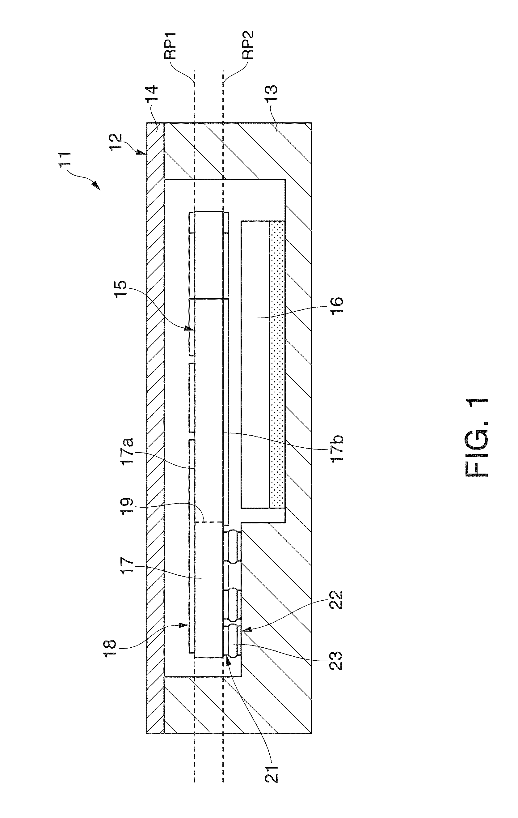
[0047]FIG. 1 schematically shows a configuration of a gyro sensor 11 according to the first embodiment. The gyro sensor 11 includes a box-shaped container 12, for example. The container 12 includes a container main body 13 and a lid member 14. The opening of the container main body 13 is air-tightly covered by the lid member 14. The internal space of the container 12 may be sealed in vacuum, for example. The container 12 functions as a rigid body. At least the lid member 14 may be formed from a conductor. When the lid member 14 is grounded, the lid member 14 may exert a shield effect for electromagnetic wave.
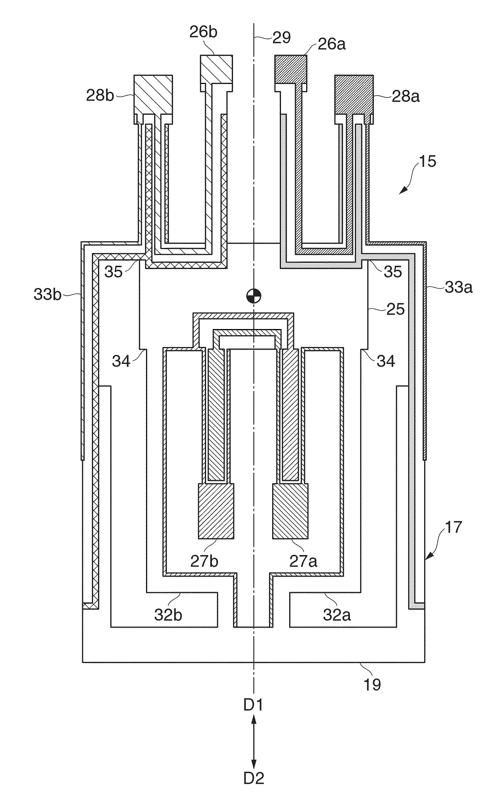
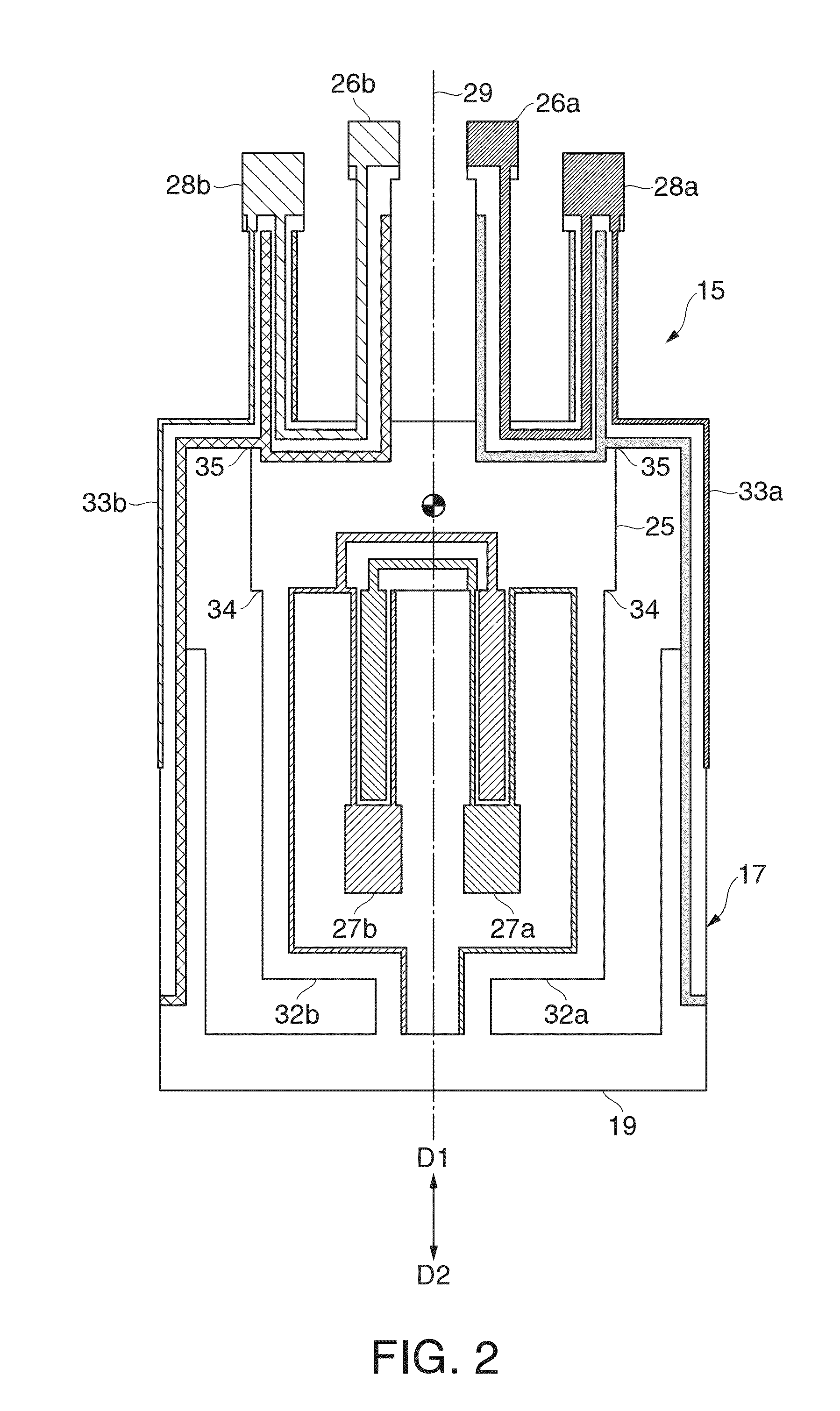
[0048]A vibrating reed 15 and an IC (integrated circuit) chip 16 are housed in the container 12. The vibrating reed 15 and the IC chip 16 are provided within the internal space of the container 12. The vibrating reed 15 includes a main body 17 and a conducting film 18. The conducting film 18 is stacked on the surfaces of the main body 17. The cond...
second embodiment
(4) Gyro Sensor
[0082]In the gyro sensor 11 according to the second embodiment, for the vibrating reed 15, third vibrating arms 63 are used in place of the above described third vibrating arms 28a, 28b. As shown in FIG. 12, a first groove 64 is formed on the front surface (first surface) 17a of the third vibrating arm 63 and a second groove 65 is formed on the rear surface (second surface) 17b of the third vibrating arm 63. The first groove 64 and the second groove 65 extend from the base of the third vibrating arm 63 toward the free end in the longitudinal direction of the third vibrating arm 63. The first groove 64 and the second groove 65 may be formed as long grooves extending over the entire length of the third vibrating arm 63.
[0083]The first groove 64 has a first wall surface 66a and a second wall surface 66b. The first wall surface 66a and the second wall surface 66b face each other. The first wall surface 66a sandwiches the piezoelectric member of the third vibrating arm 63 ...
third embodiment
(5) Gyro Sensor
[0091]As shown in FIGS. 13A and 13B, in the gyro sensor 11 according to the third embodiment, a vibrating reed 15a includes a pair of first vibrating arms 71a, 71b in place of the above described first vibrating arms 26a, 26b. In the first vibrating arm 71a, the second side surface 53 and the front surface 17a are connected to each other at a first step 72. Similarly, the side surface 53 and the rear surface 17b are connected to each other at a second step 73. The first step 72 and the second step 73 extend from the base of the first vibrating arm 71a toward the free end over the entire length of the first vibrating arm 71a, for example. The first step 72 includes a step surface 72a specifying an edge line between the second side surface 53 and itself and a vertical surface 72b crossing the step surface 72a and specifying an edge line between the front surface 17a and itself. The piezoelectric member of the first vibrating arm 71a is sandwiched between the vertical su...
PUM
 Abstract
Description
Claims
Application Information
 - R&D
- Intellectual Property
- Life Sciences
- Materials
- Tech Scout
- Unparalleled Data Quality
- Higher Quality Content
- 60% Fewer Hallucinations
Browse by: Latest US Patents, China's latest patents, Technical Efficacy Thesaurus, Application Domain, Technology Topic, Popular Technical Reports.
© 2025 PatSnap. All rights reserved.Legal|Privacy policy|Modern Slavery Act Transparency Statement|Sitemap|About US| Contact US: help@patsnap.com