RFID and product labelling integrated in knit composite tubes for fluid delivery system

a technology of composite tubes and product labels, applied in the field of composite tubes, can solve the problems of increasing the cost of labeling, increasing the cost of secondary or additional manufacturing steps, and unable to meet the wide electrical performance requirements of traditional fuel lines, and achieves the effect of avoiding all laminated seams or overlapping areas and low tooling costs

Active Publication Date: 2013-10-31
EATON INTELLIGENT POWER LTD
View PDF19 Cites 23 Cited by
  • Summary
  • Abstract
  • Description
  • Claims
  • Application Information

AI Technical Summary

Benefits of technology

[0017]The particular geometry of the composite tube can be made in an infinite number of shapes based on the ability to knit tubular sections in desired shapes. Not only can the diameter of the tube be changed, but also turns or bends and other features can be created. Intersecting sections of tubes can be attached by stitching the abutting faces to one another. Thus, the knitted pattern of fibers can be considered a continuous integral support structure which eliminates the requirement for overlapping sections at tube intersection points, thereby avoiding delamination between the layers of material.
[0028]In another preferred embodiment of the integral identification capability, the invention may include the use of radiofrequency identification (RFID). More specifically, the composite tube may include an integral RFID tag for purposes of identifying the fluid conveying component. Currently available RFID tags are capable of storing enough data that detailed information can be recorded for a product, and the data storage capability of the RFID tag may typically exceed the amount of data required for identification. Accordingly, detailed information regarding the fluid conveying component could be easily stored in the RFID tag as electronic data and accessible by an external RFID reader. This preferred embodiment includes different ways in which the RFID tag could be incorporated in the composite tube. For example, the RFID tag could be woven directly into the knitted reinforcement material in which one or more surfaces of the RFID tag could include its own fibers that are woven or otherwise knitted within the knitted reinforcement layer, or the periphery of the RFID tag could be in the form of a substrate that is secured to the knitted reinforcement layer with a dedicated stitch pattern stitched through the periphery of the substrate. Alternatively, the RFID tag could be placed between layers of the knitted reinforcement material, or the RFID tag could be introduced into the tube construction during the layup of matrix material in which the tag could be added to a selected location in the cross sectional area of the tube.

Problems solved by technology

Various efforts have been made to isolate fuel lines to ensure the fuel lines maintain the desired electrical properties; however, traditional fuel lines are unable to accommodate wide electrical performance requirements when comparing an event such as a lightning strike versus slow but incremental static buildup.
One limitation associated with fluid conveying tubes in general is that a secondary or additional manufacturing step is required to label fluid conveying components.
As one can appreciate, the final step of marking the component with a permanent label adds additional cost, as well as potential risk.
More specifically, there may be an increased probability that a component becomes mismarked or not marked at all if the component has to undergo an additional and separate processing step.
Further, it may be more difficult to track and locate the component for accurate labeling in an environment in which there may be dozens of different components manufactured at the same location within the same overall manufacturing process.
One particular problem associated with composite tubing is delamination that can occur between joined sections of tubes or layers among tubes.
Although initially these overlapping edges may provide an adequate structural connection, vibration and chemical degradation by contact of the fuel with the composite material eventually results in some degree of delamination.
In these cases, it may be impractical or impossible to use mechanical couplers at each junction due to weight and size constraints.
In order to electrically tune these metallic tubes, various static discharge and electrical isolators are required, which add cost and weight to the aircraft.

Method used


Image

  • RFID and product labelling integrated in knit composite tubes for fluid delivery system
  • RFID and product labelling integrated in knit composite tubes for fluid delivery system
  • RFID and product labelling integrated in knit composite tubes for fluid delivery system

Examples


Embodiment Construction

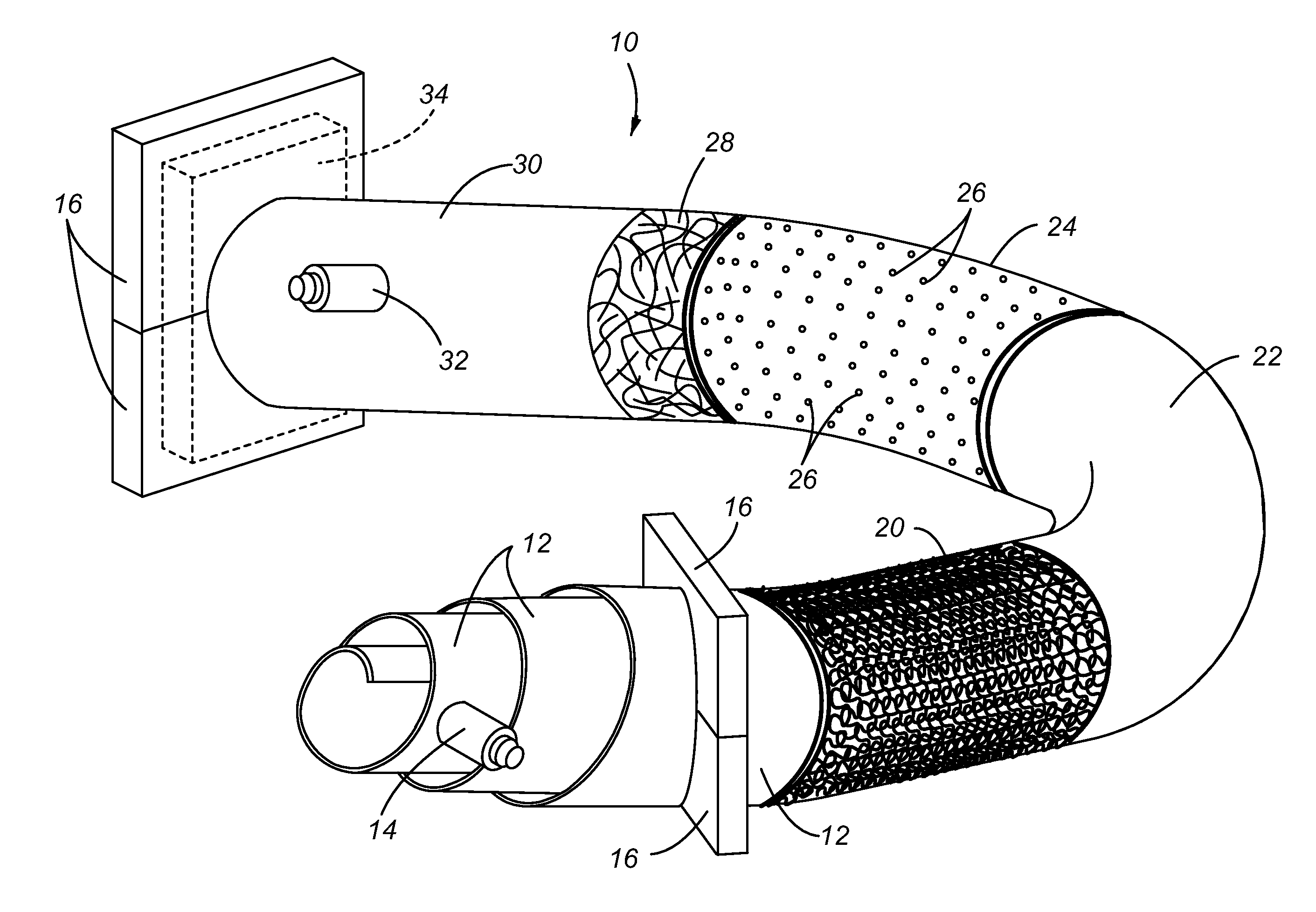
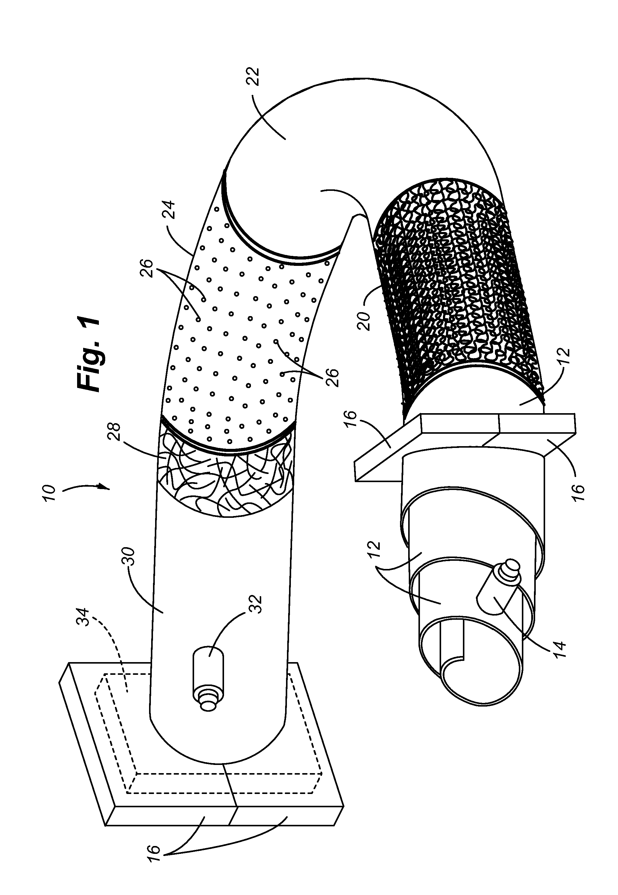
[0039]Referring to FIG. 1, a method of manufacturing the composite tube of the present invention is illustrated. The composite tube 10 is formed by a vacuum bag molding process. For illustrative purposes, the successive layers of material are shown as exposed. First, a spiraled inner bladder 12 is placed within the interior opening of a knitted reinforcement layer 20. The tubular knitted pattern formed for the reinforcement layer 20 is constructed with the previously described knitted pattern having a selected group of fibers formed in a plurality of loops. The inner bladder 12 is inflated through inflation port 14, in order to expand the knitted reinforcement layer 20 to a desired diameter or shape. Additionally, the knitted reinforcement layer 20 is shown as having a bend. The reinforcement layer can be knitted with the bend. This type of knitting to produce a bend could be similar to the formation of a bend in a woven garment, such as the heel portion of a knitted sock or slipper...


PUM

PropertyMeasurementUnit
thicknessaaaaaaaaaa
diameteraaaaaaaaaa
sizeaaaaaaaaaa

Abstract

The composite tube comprises a tubular arrangement of knitted fiber having plurality of interlocking loops. The knitted pattern allows for variable electrical, mechanical and geometrical options. A matrix material is applied over the knitted fiber pattern and is allowed to cure. The matrix material may be applied by a vacuum bag molding process. The flexible knitted reinforcing layer allows use of an inflatable bladder to hold the reinforcing layer in the desired shape, thereby facilitating tube constructions of varying shapes and diameters. Continuous application of the matrix material avoids overlapping seams that are prone to delamination. Identification and labeling of the composite tube may be achieved with distinguishing knitted patterns having different types and colors of knitted fibers within the knitted reinforcing layer. A clear or translucent matrix material enables viewing of the underlying knitted patterns. Identification may also include RF ID tags Incorporated directly within the knitted reinforcing layer.

Description

CROSS REFERENCE TO RELATED APPLICATIONS[0001]This application is a continuation-in-part application of co-pending application Ser. No. 12 / 983,069 filed on 31 Dec. 2010 and entitled: Composite Tube For Fluid Delivery System, of which said application is hereby incorporated by reference in its entirety.FIELD OF THE INVENTION[0002]The present invention relates to composite tubes used in fluid delivery systems, and more particularly, to composite tubes having a knitted reinforcement layer and integral identification including an RFID tag and labeling knitted within the knitted reinforcement layer.BACKGROUND OF THE INVENTION[0003]Polymer based compositions are becoming increasingly used in a variety of different technological applications to include vehicle and aerospace applications. Polymer based composites are used in not only structural applications, but also in construction of system components in order to control the electrical conductivity and resistivity of the components. Polyme...

Claims


Application Information

Patent Timeline
Patent Type & Authority Applications(United States)
IPC IPC(8): F16L55/00
CPCF16L55/00B29C70/446B29C70/882B29L2023/22F16L9/128F16L9/125F16L2201/60B29C2037/80B29C70/54B29C70/08B29C70/86
Inventor SCHOOLEY, NICHOLAS CLANCYMARETICH, DAVID ETHANNEAL, JON WALLACESTATLER, III, RICHARD L.BREAY, CLIFTON P.
Owner EATON INTELLIGENT POWER LTD
Why Eureka
Try Eureka