

Vibrating element, gyro sensor, electronic apparatus and moving object
a technology of vibrating elements and gyro sensors, applied in the direction of generators/motors, acceleration measurement using interia forces, instruments, etc., can solve the problems of unwanted signals, deterioration of noise characteristics and temperature characteristics of the vibrating element, and inability to generate the maximum motion of the second vibrating arm
- Summary
- Abstract
- Description
- Claims
- Application Information
AI Technical Summary
Benefits of technology
Problems solved by technology
Method used
Image

Examples
first embodiment
1. Configuration of Gyro Sensor
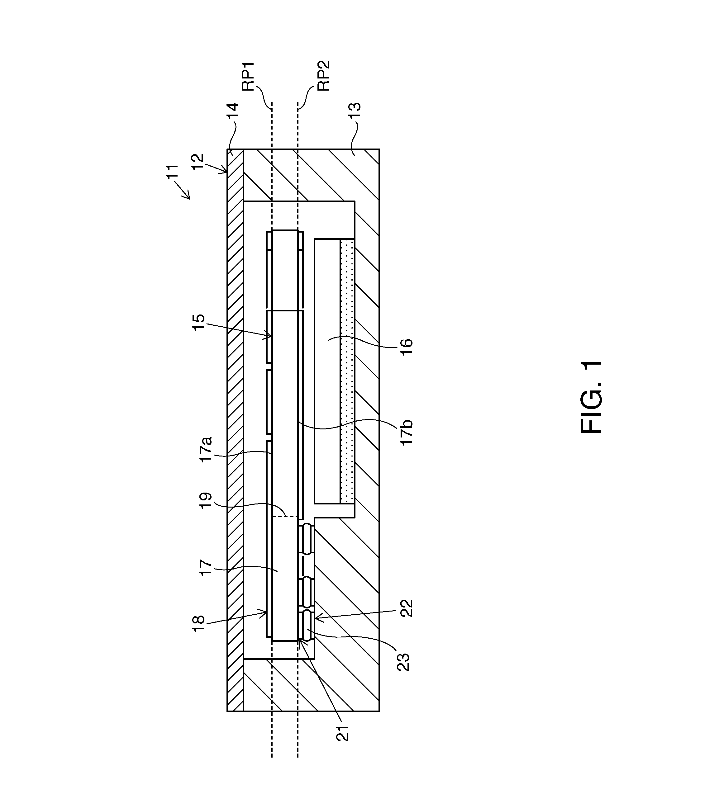
[0042]FIG. 1 schematically shows the configuration of a gyro sensor 11 according to a first embodiment. The gyro sensor 11 has a container 12, for example, in the shape of a box. The container 12 includes a container main body 13 and a lid member 14. An opening of the container main body 13 is covered by the lid member 14 in an air tight manner. The inner space of the container 12 can be sealed, for example, in a vacuum. The container 12 functions as a rigid body. At least the lid member 14 can be made of a conductor. When the lid member 14 is grounded, the lid member 14 can exert a shielding effect against electromagnetic waves.
[0043]A vibrating element 15 and an IC (integrated circuit) chip 16 are housed in the container 12. The vibrating element 15 and the IC chip 16 are arranged within the inner space of the container 12. The vibrating element 15 includes a main body 17 and an electrically conductive film 18. The electrically conductive film 18 is ...
second embodiment
3. Gyro Sensor
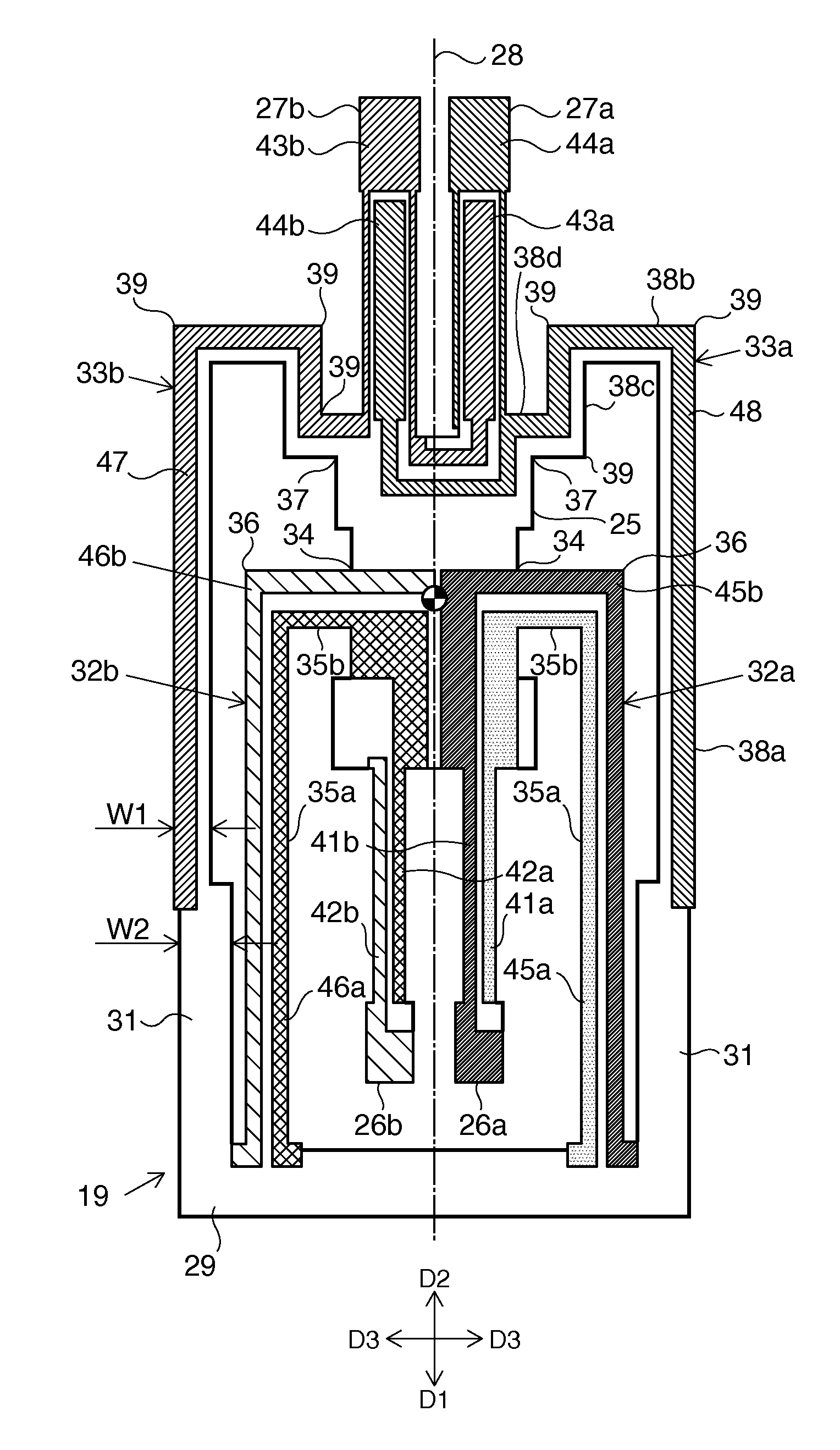
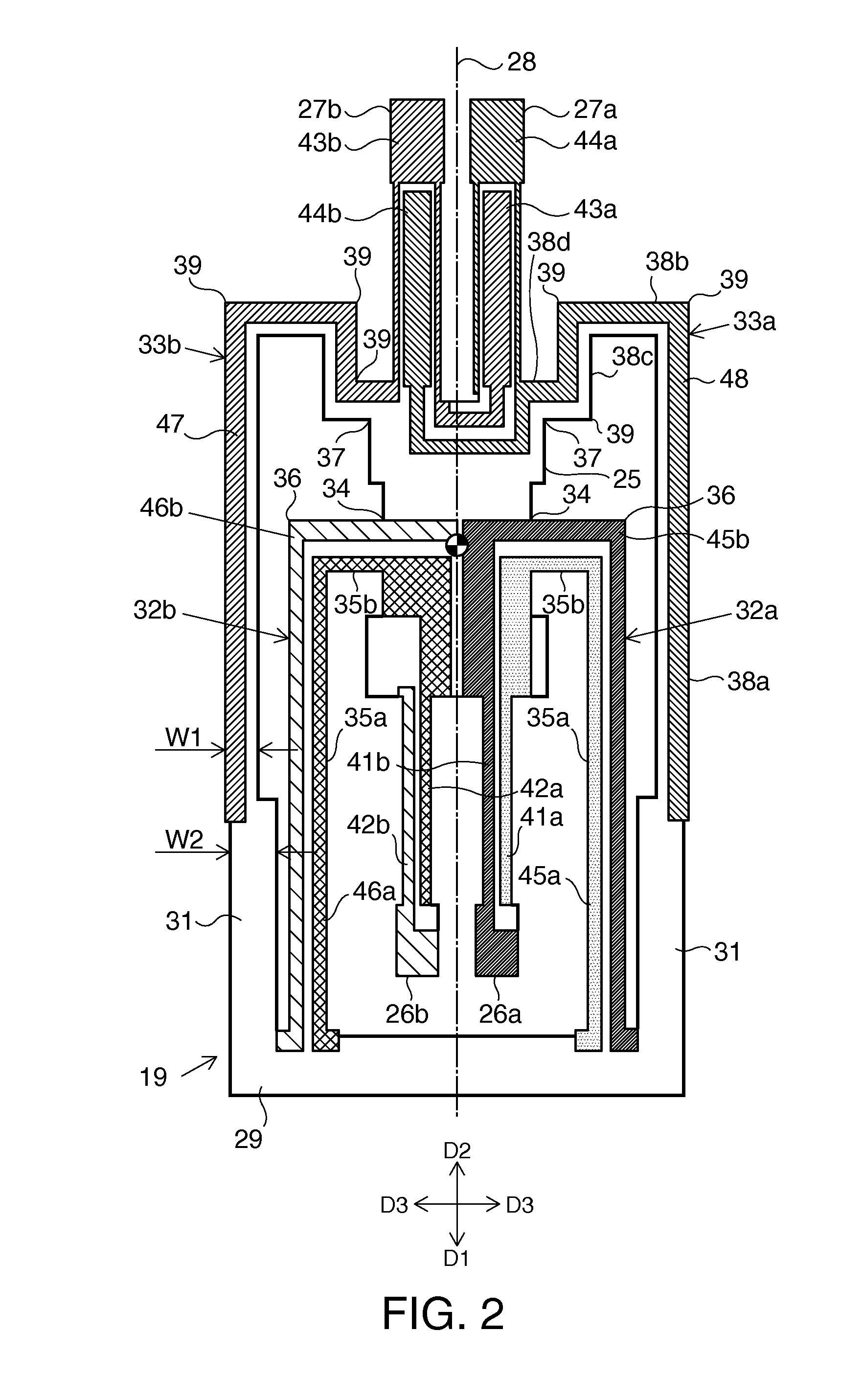
[0069]FIGS. 7 and 8 schematically show a vibrating element 15a incorporated in a gyro sensor according to a second embodiment. In this vibrating element 15a, the pair of first vibrating arms 26a, 26b function as a pair of vibrating arms for driving, and the pair of second vibrating arms 27a, 27b function as a pair of vibrating arms for detection. The first detection electrodes 41a, 41b are fixed to the one second vibrating arm 27a. The second detection electrodes 42a, 42b are fixed to the other second vibrating arm 27b. The first drive electrodes 43a, 43b are fixed to the first vibrating arms 26a, 26b, respectively. The second drive electrodes 44a, 44b are fixed to the first vibrating arms 26a, 26b, respectively. The first detection wires 45a, 45b are fixed to one second suspension arm 33a. The second detection wires 46a, 46b are fixed to the other second suspension arm 33b. The first drive wire 47 and the second drive wire 48 are fixed to the first suspension arms 32b...
third embodiment
4. Gyro Sensor
[0070]FIG. 9 schematically shows a vibrating element 15b incorporated in a gyro sensor according to a third embodiment. In this vibrating element 15b, each of the first suspension arms 32a, 32b includes six straight arms 55a to 55f. The straight arm 55a linearly extends in the second direction D2 from the first fixed piece 29. The straight arm 55f extends in the third direction D3 from the first connecting part 34. The straight arm 55e extends in the first direction D1 from the distal end of the straight arm 55f. The straight arm 55a and the straight arm 55e extend on the same straight line. The straight arm 55c extends parallel to the second fixed piece 31. The straight arm 55c is arranged at a position further away from the second fixed piece 31, compared with the straight arms 55a, 55e. The straight arm 55b connects one end of the straight arm 55c to the distal end of the straight arm 55a. The straight arm 55d connects the other end of the straight arm 55c to the di...
PUM
 Abstract
Description
Claims
Application Information