
System and Method to Detect Accumulator Loss of Precharge
- Summary
- Abstract
- Description
- Claims
- Application Information
AI Technical Summary
Benefits of technology
Problems solved by technology
Method used
Image

Examples
Embodiment Construction
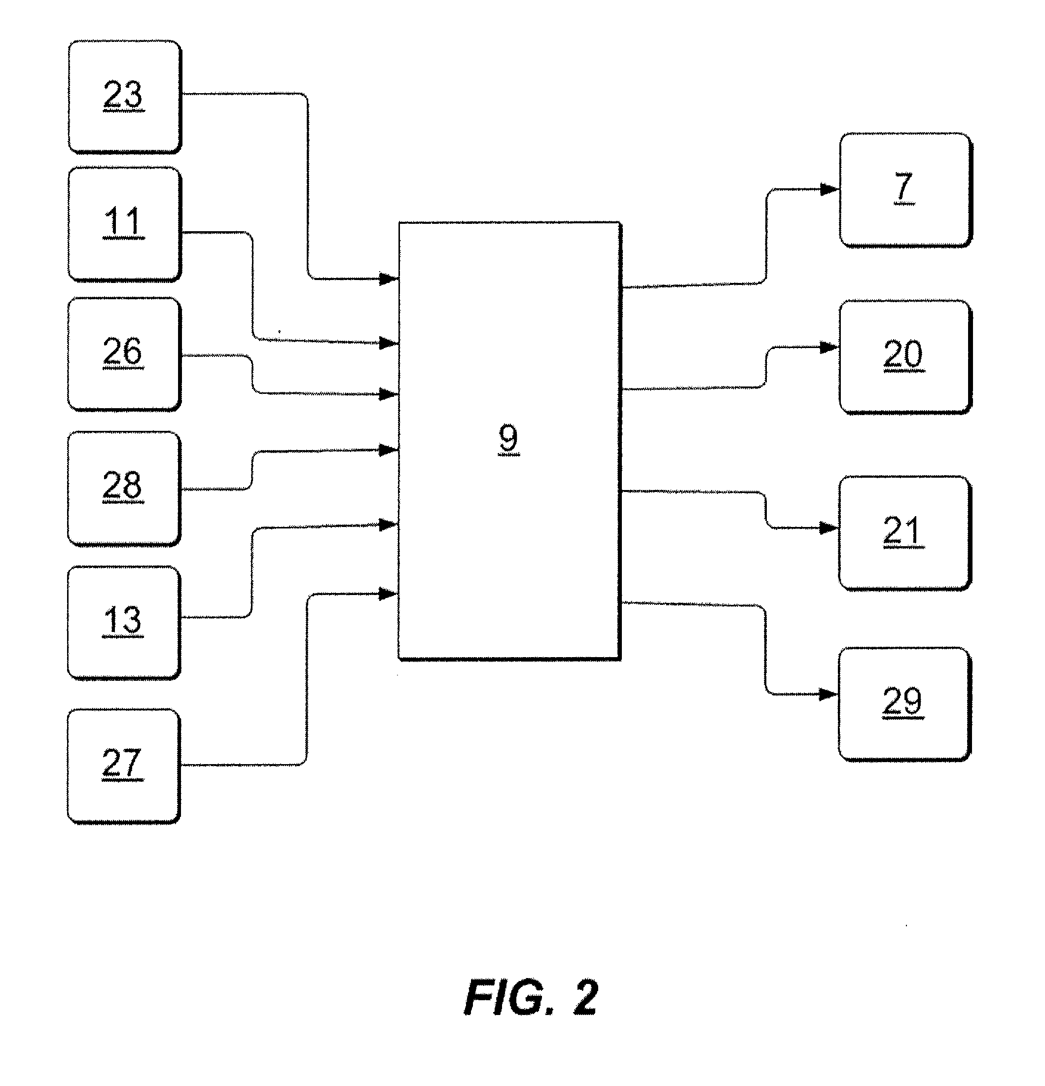
[0017]The present disclosure provides a system and method for detecting a loss of accumulator precharge in an automated manner. In overview, the system includes a fluid pressure sensor, a nitrogen gas temperature sensor, a microprocessor, an engine speed sensor, and a hydraulic fluid temperature sensor. A two-part protocol employs two phases, namely a cold start phase and a steady state phase, to determine accumulator gas remaining, with data gleaned from the cold start phase being used in the steady state phase.
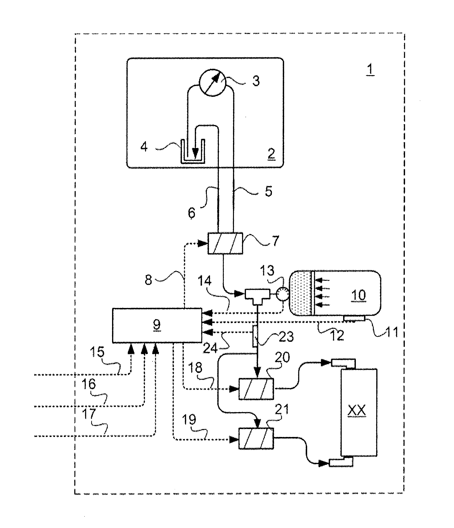
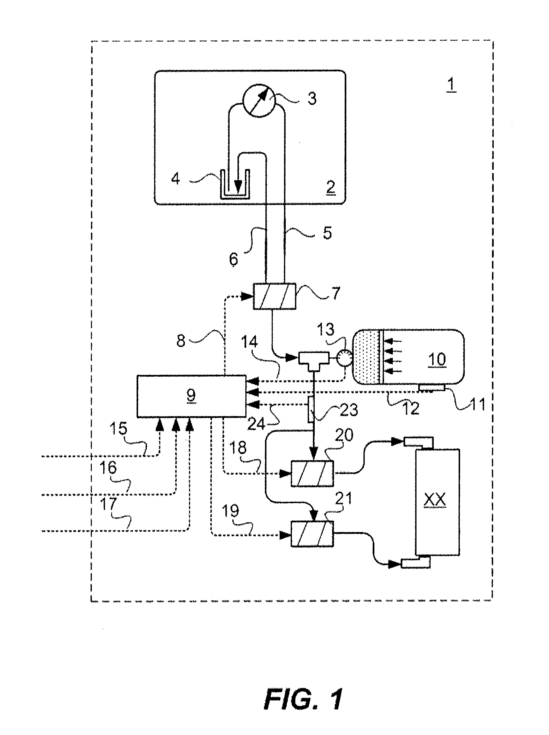
[0018]Turning to a detailed description of an embodiment, FIG. 1 is a system schematic diagram showing a machine hydraulic circuit 1 including a machine hydraulic source 2 which includes a fluid source pump 3 and fluid return 4, the machine hydraulic source 2 being linked to the remainder of the machine hydraulic circuit 1 via an outlet line 5 and an inlet line 6. The outlet line 5 and inlet line 6 are selectively controlled through a three-position electrically actuated val...
PUM
 Abstract
Description
Claims
Application Information