Tubular running device and method

a tubular and running technology, applied in the direction of drilling casings, drilling pipes, borehole/well accessories, etc., can solve the problems of difficult to control difficulty in using slip-type elevators to restrain the section of tubular octg to be added, and difficulty in adjusting the grip

Active Publication Date: 2013-11-07
2M TEK
View PDF2 Cites 23 Cited by
  • Summary
  • Abstract
  • Description
  • Claims
  • Application Information

AI Technical Summary

Benefits of technology

[0059]It is a further object of this invention that the hydraulic or pneumatic cylinders may be coupled to a weight compensation control system whereby the activation of the weight compensation system will provide for the tubular OCTG to be lowered in a controlled fashion into the tubular OCTG already secured in the rotary table on the drill floor and utilizing the weight compensation system will effectively give the tubular OCTG zero weight in gravity and protect the threads of the tubular OCTG during stabbing operations, for make-up or breakout operations.
[0060]It is a further object of this invention that the weight compensation control system can be a separate system installed above the tubular running assembly actuator and below the top drive whereby the activation of the weight compensation system will provide for the tubular OCTG to be lowered in a controlled fashion into the tubular OCTG already secured in the rotary table on the drill floor and utilizing the weight compensation system will effectively give the tubular OCTG zero weight in gravity and protect the threads of the tubular OCTG during stabbing operations, for make-up or breakout operations.
[0061]It is a further object of the invention to provide a method of running tubular OCTG into and / or out of a well bore, comprising the steps of: locating a tubular OCTG and extending links and transfer elevators around the tubular OCTG; latching transfer elevator around tubular OCTG; moving a top drive with a tubular running assembly in an upward movement causing the captured or retained tubular OCTG into a vertical position above a tubular OCTG already secured in the rotary table on the drill floor; activation of the weight compensation system to lower the tubular OCTG in a controlled fashion into the aforementioned tubular OCTG already secured in the rotary table; engage the threads of the upper tubular OCTG in the threads of the tubular OCTG already secured in the rotary table on the drill floor; activate the hydraulic, pneumatic, mechanical or the like actuator, into the release position producing relative movement of the members causing the rolling supports with or without a central spindle to retract radially through openings in the tube; lowering the tubular running assembly onto or into the tubular OCTG; activate the hydraulic, pneumatic, mechanical or the like actuator into the latch position producing relative movement of the members causing the rolling supports with or without a central spindle to protrude radially through openings in the tube; once the rolling supports with or without a central spindle are engaged on the inner or outer wall of the tubular OCTG, rotate the top drive mechanism to cause the upper tubular OCTG threads to engage correctly with the mating threads of the tubular OCTG already secured in the rotary table on the drill floor and thereby connecting both tubular OCTG into one continuous member; lifting the tubular OCTG members in an upward direction by the tubular running assembly connected to the top drive while unsetting the slip mechanism of the retaining device in the rotary table to allow the joined tubular OCTG to be lowered into the well bore. By reversing the process the tubular OCTG members can be removed from a well bore if desired.

Problems solved by technology

It is also a very dangerous task with personnel often having to be located on a small platform suspended up to 50 feet from the rotary table or drilling rig floor and the power tong tethered to a steel cable under high loads.
Where a top drive system is used to make up the connection, the use of a slip type elevator to restrain the section of tubular OCTG to be added may be problematic, due to the configuration of the top drive apparatus on the drilling platform.
While this is an advancement over the traditional approach as it requires substantially less equipment, it does however have serious drawbacks in the form of potential damage it may cause to the outer or inner surface of the tubular OCTG.
These grapple / dies also tend to be very sensitive to varying changes in tubular weight and diameters and therefore require a large resource of alternative sizes for each tubular OCTG size or weight to be run.
The possibility of loading one side of the tubular OCTG can present serious consequences for the integrity of the tubular OCTG and its ability to withstand down-hole pressures in the borehole.
This in turn may also result in premature failure of the grapple / dies or impede their ability to act correctly on the tubular OCTG.
Thirdly, as the grapple / dies tend to be suspended on the outside of the member for internal gripping tools with no means of constraint they can become a huge safety issue if the rotational drive is engaged whilst the probe is not inside the tubular OCTG.
The centrifugal forces cause the grapple / dies to separate from the tool member, causing them to become entangled in the steel framework of the rig and potentially becoming dangerous objects falling from the derrick structure.
Fourthly, traditional methods of tool design permits the slip assemblies, bodies or inserts to potentially friction bond or become adhered to each other under heavy load conditions.
If these slip assemblies, bodies or inserts become frictionally adhered, this can cause serious problems, especially in a well control situation.
When it comes to handling tubulars OCTG's where a single connector is used the failure of this single connector has the potential for catastrophic consequences.
A first disadvantage of previous attempts is in the design of the member containing the inclined or tapered ramps which include areas of deeper than necessary pockets as well as sharp corners.
A second disadvantage of previous attempts is that they were ineffective in providing the rotational torque capacity required for the make-up or break-out of said tubular OCTG.
This method of energizing the balls or rolling elements is ineffective in applying an adequate amount of preload force on the balls or rolling elements to create an indentation of sufficient size and depth to apply the required torque without slipping.
These designs do not allow the operator the ability to hydraulically, pneumatically, or mechanically control these preload forces to create the required indentations for applying torque.
A third disadvantage of this previous attempts is in the design of the openings or slots and its role in applying torque.
Previous attempts cage housing openings make no attempt to aid in the application of torque.
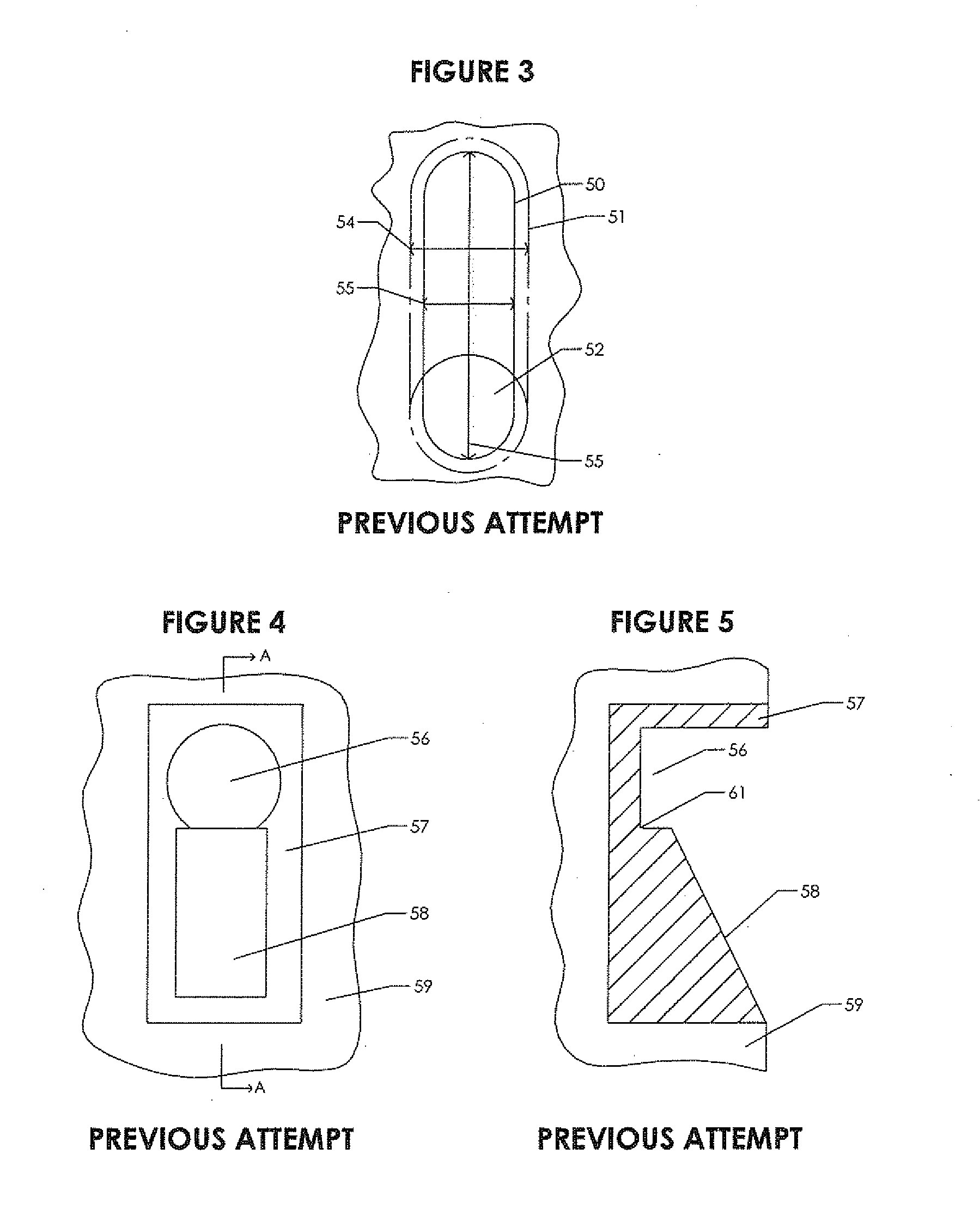
A fourth disadvantage of this previous attempts is the use of elongated slots where the length of the slot is substantially longer than the diameter of the ball or rolling element.
A fifth disadvantage of these elongated slots is the large cavity created between the elongated slots and the inclined surfaces.
This cavity may become filled with debris or other materials than can inhibit or prevent the function of the gripping device.
A sixth disadvantage of the elongated slot design is that the slot must contain a means of retaining the ball or rolling element along the longer sides of the slot because the ball or rolling element must be allowed to travel the entire length of the slot.
This aspect of the design prevents the sides or edges of a rolling element to protrude from the cage housing which limits the options for the shape of the rolling element.
The shape of the rolling element can also limit the range of outer or inner surface diameters which can be gripped with a given gripping device configuration.
A seventh disadvantage of the elongated slots is amount of material that is removed from the cage housing diminishing the structural integrity of the cage housing.
Transporting tools to or from a drilling rig, loading, and unloading of these tools, especially on an offshore location, as well as handling of these tools can create damages.
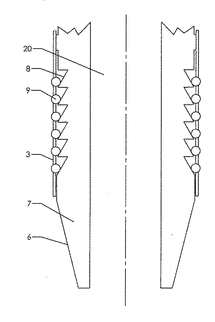
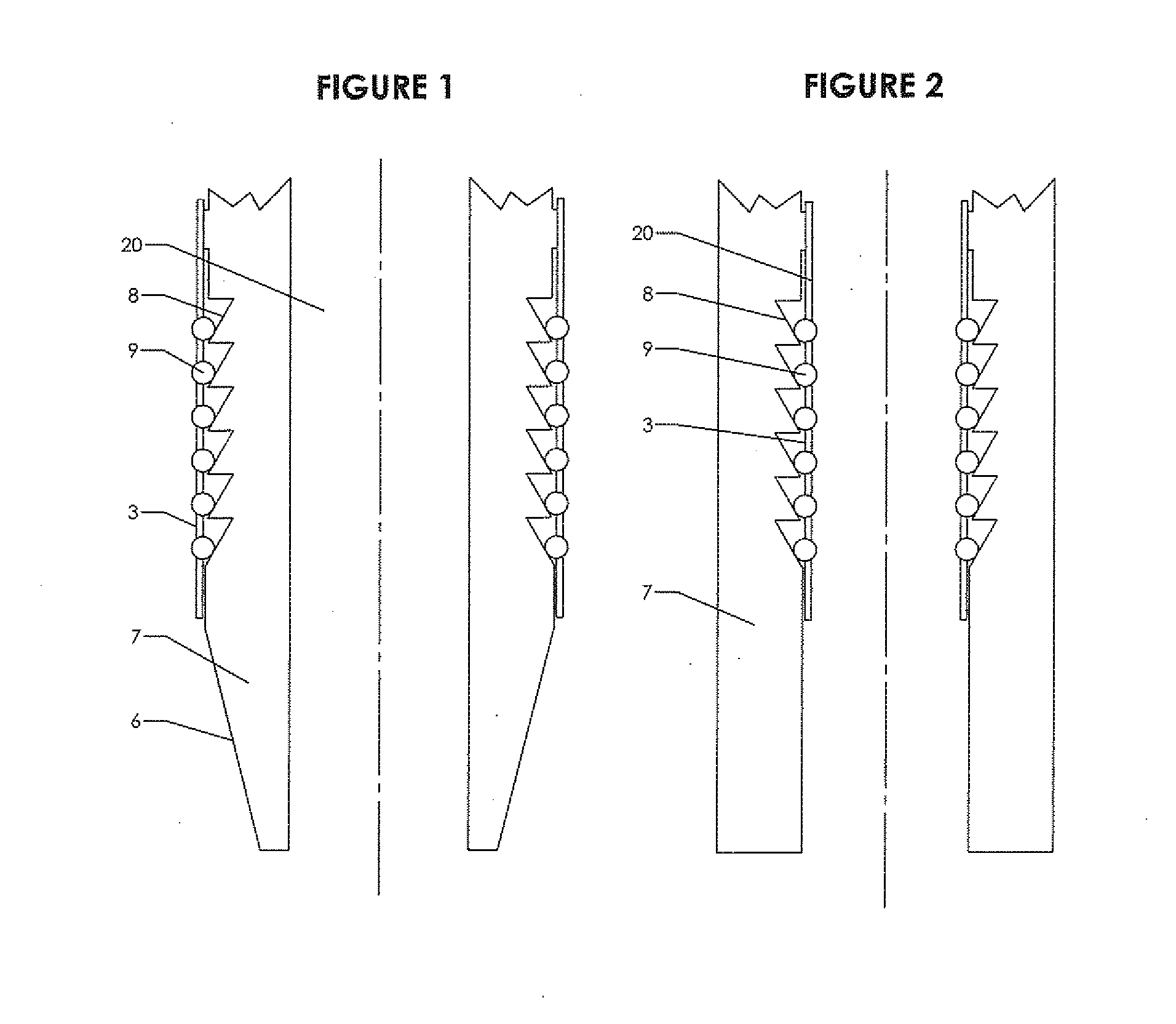
A eighth disadvantage of previous attempts is the means of disengaging or releasing an internal gripping device during entry into a tubular whereby frictional forces acting upon the outer surface of the cage housing imposed from the internal surface of the tubular act to urge the cage housing in a direction such that the rolling elements move toward the deep end of the inclined surfaces, thus released position.
This “dragging” of the cage housing produces wear on the cage housing as well as the internal surface of the tubular.
This dragging can also cause damage to the internal tubular threads.
A ninth disadvantage of previous attempts is in the design of the member containing the inclined or tapered ramps which include areas of deeper than necessary pockets as well as sharp corners.
These sharp corners also create areas prone to corrosion and or rusting.
A tenth disadvantage of previous attempts is in the use of multiple components such as small springs, plungers, inserts, biasing devices, etc which are all made unnecessary by the embodiments of the present invention.
All of these components must be held in place via means such as press fitting, adhesives, threaded fasteners, etc. which all initiate the potential for failures.
It is well known that as the number of parts is increased for a single mechanical device so does the odds of failure.
The corresponding machining or manufacturing processes for these components is greatly complicated by the use of these components.
The complexity and tight tolerances required to successfully manufacture these components substantially increases the overall cost of the gripping device.
An eleventh disadvantage of previous attempts again in the use of multiple components such as small springs, plungers, inserts, biasing devices, etc is that should any of these small components become loose or free from constraint, they can potentially fall into the wellbore.
This potential is very high due to the jarring and shock loads the gripping device will experience in service as well as transport.
These shock loads can loosen threaded fasteners or other means of retention.
Also, heat and or extreme cold can affect retention means such as adhesives, press fit and interference fit tolerances.
Should any of these components become free from constraint, the elongated slots will allow these items to depart from the assembly, thereby becoming major safety hazards with the potential for serious damage to personnel or structures from flying debris.
Materials or items which unintentionally fall into the wellbore create an array of very costly problems.
A twelfth disadvantage of the previous attempts utilizing the aforementioned inserts which are press fit or otherwise attached to the member containing the inclined surfaces is in the non destructive testing of these components after each use in the field.
Components which are press fit or adhered using adhesives are generally very difficult or impossible to remove for inspection purposes.
This means that these parts will likely not be removed thereby possibly hiding a crack or damage.
If a threaded fastener is used, these threads create stress risers and areas for corrosion to begin.

Method used


Image

  • Tubular running device and method
  • Tubular running device and method
  • Tubular running device and method

Examples


second embodiment

[0133]FIG. 11 is a sectioned view of a rolling support 9 with a central spindle 34 partially protruded from an opening 4 in the cage housing 3. The rolling support 9 is retained within the assembly via spindle 34. The rolling support 9 is only allowed to move radially relative to cage housing 3. This makes the movement of the rolling support 9 very responsive to movement of the cage housing 3.

[0134]FIG. 12 is a side view of a second embodiment of the cage housing 3 of FIG. 11 with a rolling support with a central spindle 9 mounted within an opening 4. The opening 4 has substantially flat sides 67 and substantially curved ends 75. The flat sides 67 are aligned with the longitudinal axis of cage housing 3. The sides 66 of the rolling support with central spindles 9 are allowed to protrude through opening 4 and are close in proximity to the sides of the opening 67. Undercut feature 69 of the cage housing 3 retains rolling support with central spindles 9 within the assembly via spindle ...

third embodiment

[0146]FIG. 24 is a front elevation view of a rolling support with a spindle 37 through its central axis and a substantially flat surface 38 on its outermost surface.

[0147]FIG. 25 is a side elevation view of the rolling support of FIG. 24 with a spindle 37 through its central axis.

[0148]FIG. 26 is a front elevation view of a third embodiment of a rolling support with no spindle.

[0149]FIG. 27 is a side elevation view of the rolling support of FIG. 26 with no spindle.

fourth embodiment

[0150]FIG. 28 is a front elevation view of a rolling support with a spindle 39 through its central axis and curved outermost surface 40.

[0151]FIG. 29 is a side elevation view of the rolling support of FIG. 28 with a spindle 39 through its central axis.

[0152]FIG. 30 is a front elevation view of a fourth embodiment of a rolling support with no spindle.

[0153]FIG. 31 is a side elevation view of the rolling support of FIG. 30 with no spindle.


PUM


Abstract

A method and apparatus for running tubular(s) into a well bore for use with a top drive or power swivel comprising a make-up assembly with inner and outer members, one of which has an array of ramped or inclined surface(s) while the other is an inner or outer cage with rolling support(s) with or without a central spindle and openings which may also be referred to as tubular engagement apparatus wherein relative movement of the members urges the rolling support(s) to protrude radially through the openings to engage a tubular internally or externally. Also provided is an elevator assembly with elevator links and transfer elevators to position tubular for engagement by the make-up assembly.

Description

BACKGROUND OF THE INVENTION[0001]The present invention relates to a device and method for the gripping and or handling of tubular members. These tubular members vary widely in size, shape, thickness, function, orientation while in service, and industries served. They can be pipes, steel structures, columns, tubing, casing, culverts, pilings, caissons, pipelines, etc. A non-inclusive list of uses for the present invention includes:[0002]1) A first use is in the construction of oil and gas wells where it is usually necessary to drill and line the well bore with a string of steel pipes commonly known as tubulars, casing, tubing, or generically as oil country tubular goods (“OCTG”).[0003]2) A second use is in the abandonment or decommissioning of oil and gas wells where it is usually necessary to remove the steel pipes commonly known as tubulars, casing, tubing, or generically as oil country tubular goods (“OCTG”), steel structures, pilings, caissons and or pipelines[0004]3) A third use...

Claims


Application Information

Patent Timeline
Patent Type & Authority Applications(United States)
IPC IPC(8): E21B19/06
CPCE21B19/06E21B19/168E21B19/07E21B19/155E21B19/16
Inventor MCINTOSH, RICHARDBAUDOIN, TOBY SCOTT
Owner 2M TEK
Why Eureka
Try Eureka