Eureka AIR delivers breakthrough ideas for toughest innovation challenges, trusted by R&D personnel around the world.

Biomass pyrolysis furnace

Inactive Publication Date: 2013-11-07
XIAO GUOXIONG
View PDF4 Cites 6 Cited by
  • Summary
  • Abstract
  • Description
  • Claims
  • Application Information

AI Technical Summary

Benefits of technology

The present invention is a biomass pyrolysis furnace that can efficiently and effectively convert wood into energy. It is easy to operate, has a high biomass pyrolysis efficiency, and produces a high amount of pyrolysis recovery rate of wood tar.

Problems solved by technology

Due to blocked by the thick biomass layer, the water vapor can't pass easily.
The wood gas has low heating value and is a non-condensable gas, so it has to be evacuated which may cause environmental pollution and waste of energy.
However the quickly burning of the wood tar gas and the wood gas at the top of the furnace brings danger to the operator, while a lot of flammable gas is discharged, resulting in waste of energy.
The yield of the biomass charcoal and the wood tar is low.
The disadvantages of such device for the pyrolysis of biomass fuel are as follows: 1. it is heavy labor and unsafe to lever every few hours; 2. long time for the pyrolysis of biomass, low production efficiency and high production cost; 3. the yield of the biomass charcoal and wood tar is few, a large amount of charcoal fuel is converted into the wood gas and wood vinegar that is a big waste of the raw material.
In order to ensure the cooling effect, the height of the recovery tower is usually increased by 20˜50 m. Since the distance between the bottom of the tower and the ground is short, once the path of the recovery tower is blocked by the wood tar, it is hard to clean the path with a tool.

Method used


Image

  • Biomass pyrolysis furnace
  • Biomass pyrolysis furnace
  • Biomass pyrolysis furnace

Examples


Embodiment Construction

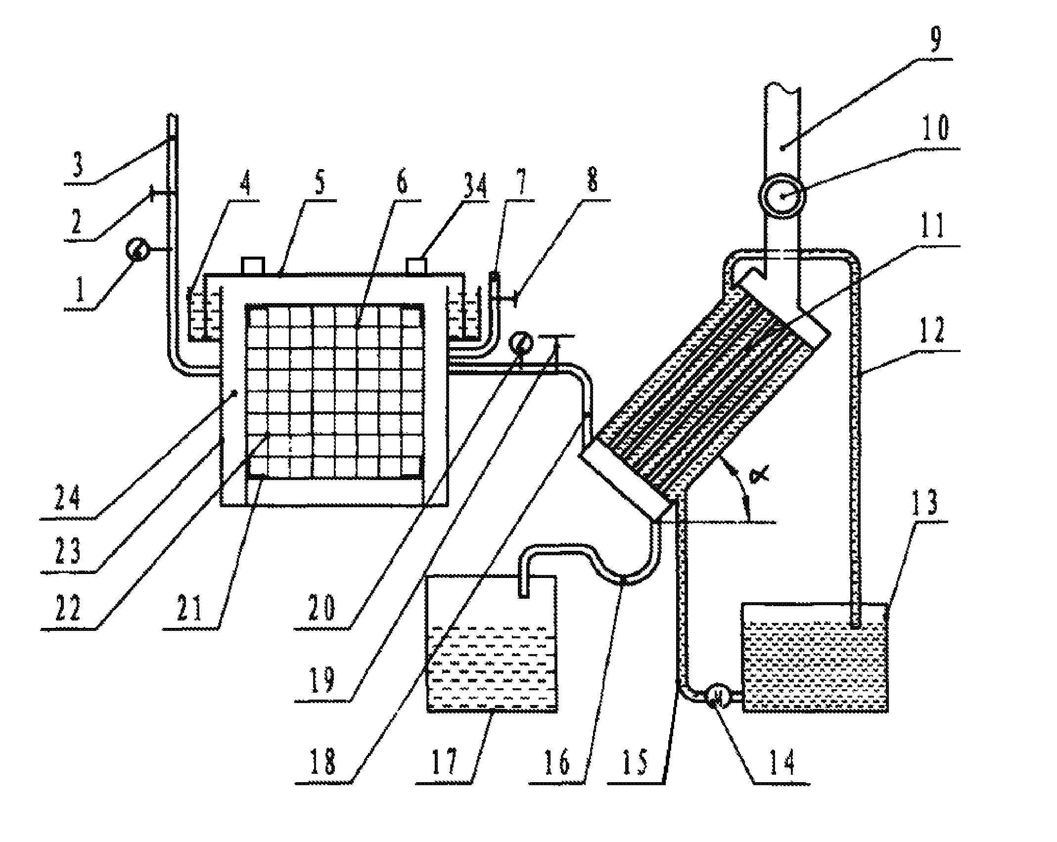
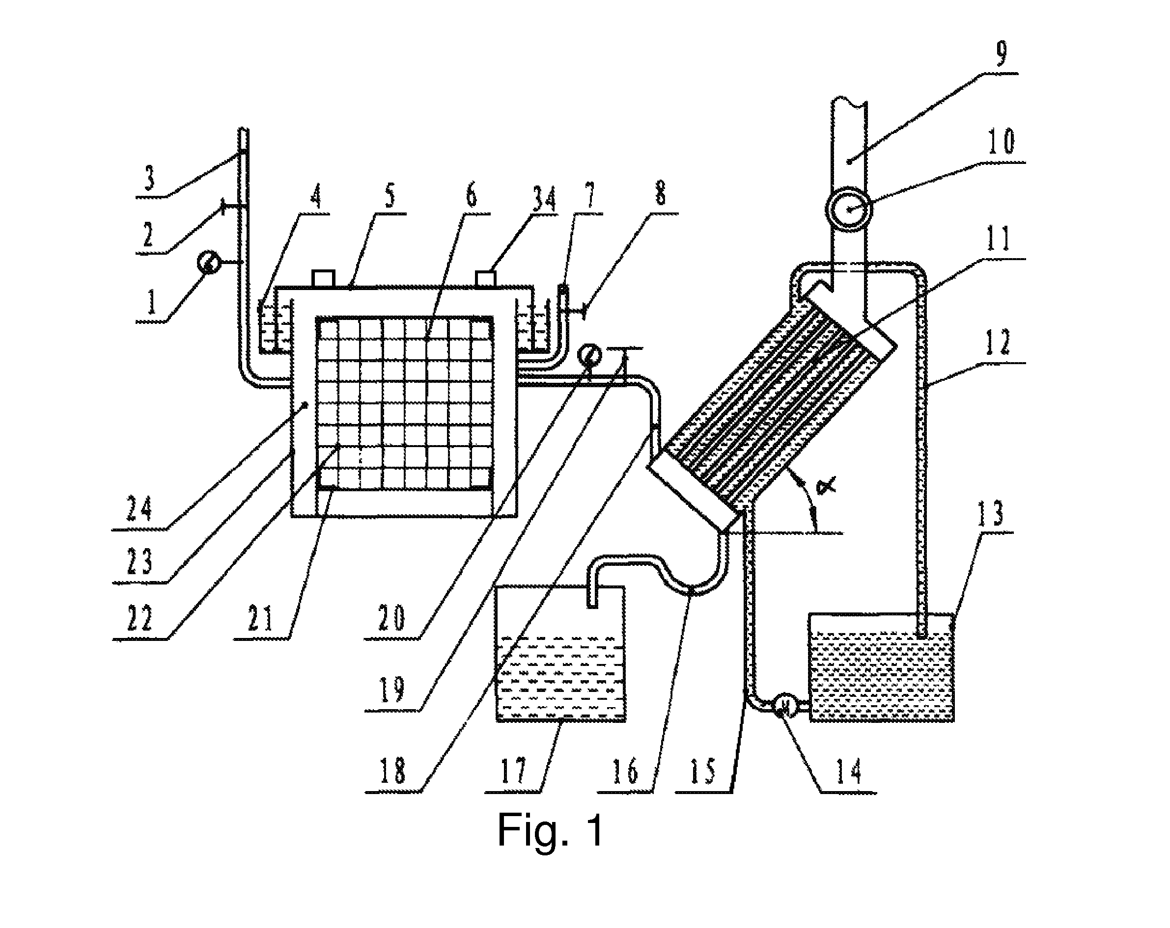
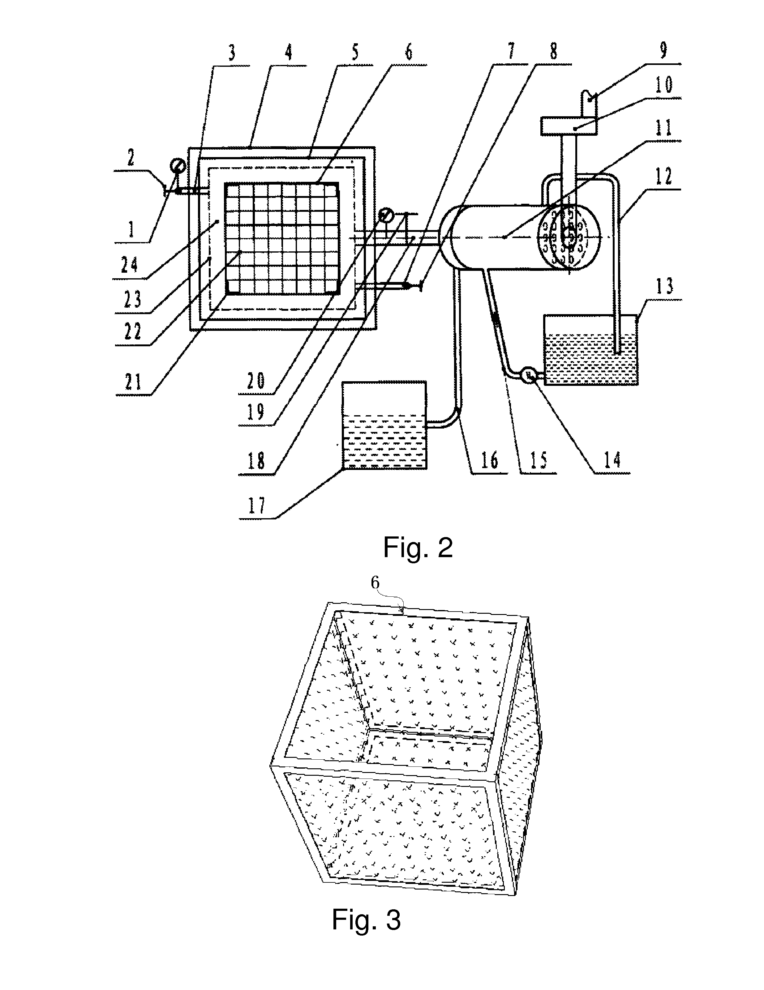
[0058]A biomass pyrolysis furnace as shown in FIG. 1 and FIG. 2, comprises a furnace shell 23, a furnace container 6, an exhaust pipe 3, an intake pipe 7, a smoke pipe 18, a recovery tower 11. The smoke pipe 18 is installed on the furnace shell 23, and the furnace container 6 is installed in the furnace shell 23. The bottom of the furnace container 6 and periphery thereof are provided with a plurality of mesh holes. An exhaust gap 24 which may be used for discharge of vapor is provided between the furnace container 6 and the inner surface of the wall of the furnace shell 23. The smoke pipe 18 is connected to the furnace shell 23 at one end thereof, and to the recovery tower 11 at the other end thereof.

[0059]The pyrolysis furnace shell 23 may be a six-side closed tank comprising a shell body and a water-seal cover 5. At its periphery, the furnace mouth of the shell body is provided with an U-shaped water-seal slot 4 which is full of water, as shown in FIGS. 7 and 8. The water-seal co...


PUM


Abstract

A biomass pyrolysis furnace comprises a furnace shell (23), a furnace container (6), an exhaust pipe (3), a smoke pipe (18), a recovery tower (11), and an intake pipe (7), wherein the smoke pipe (18) is installed on the furnace shell (23); the furnace container (6) is installed in the furnace shell (23); the bottom of the furnace container (6) and the periphery thereof are provided with a plurality of mesh holes; an exhaust gap (24) is provided between the furnace container (6) and the inner wall of the furnace shell (23); the smoke pipe (18) is connected to the furnace shell (23) at one end thereof, and to the recovery tower (11) at the other end thereof. The furnace shell (23) is provided, on one side at the upper end, with a flue hole and an intake pipe (7), and the exhaust pipe (3) is provided on the opposite side of the furnace shell (23). The pyrolysis furnace has a short time of biomass pyrolysis, high efficiency, high pyrolysis recovery rate of wood tar, and a simple structure, and therefore it is convenient to operate and maintain.

Description

FIELD OF THE INVENTION[0001]The present invention relates to a device for the biomass fuel pyrolysis, specifically relates to a biomass pyrolysis furnace.BACKGROUND OF THE INVENTION[0002]The direct-heating pyrolysis furnace is a closed furnace, such as a pyrolysis furnace of preventing oxidation (Patent No.: CN200920062938.0), the side walls and the upper side of this pyrolysis furnace are all non-porous; and the bottom of the said furnace has gap for discharging water vapor, wood vinegar, wood tar and wood gas and the like. The biomass is renewable energy source having high moisture content. At the beginning of the pyrolysis, the moisture in the biomass is evaporated firstly. After the water changing into vapor, it must pass through the thick biomass and then enter the smoke flue to be discharged. Due to blocked by the thick biomass layer, the water vapor can't pass easily. Thus, the ignition temperature rises continuously over time, up to 600° C. and higher, while a large amount o...

Claims


Application Information

Patent Timeline
IPC IPC(8): C10B49/02
CPCC10B49/02C10B53/02C10C5/00Y02E50/10
Inventor XIAO, GUOXIONG
Owner XIAO GUOXIONG
Why Eureka
Eureka Blog
Learn More