
Semiconductor devices including capacitor support pads

a technology of semiconductor devices and support pads, applied in semiconductor devices, capacitors, electrical equipment, etc., can solve the problems of difficult application of growing hsgs to semiconductor devices, electrode collapse or breakage, and difficulty in ensuring the critical dimension between the lower electrodes, so as to reduce the stress caused by the support pads and applied to the lower electrodes

Active Publication Date: 2013-11-07
SAMSUNG ELECTRONICS CO LTD
View PDF5 Cites 4 Cited by
  • Summary
  • Abstract
  • Description
  • Claims
  • Application Information

AI Technical Summary

Benefits of technology

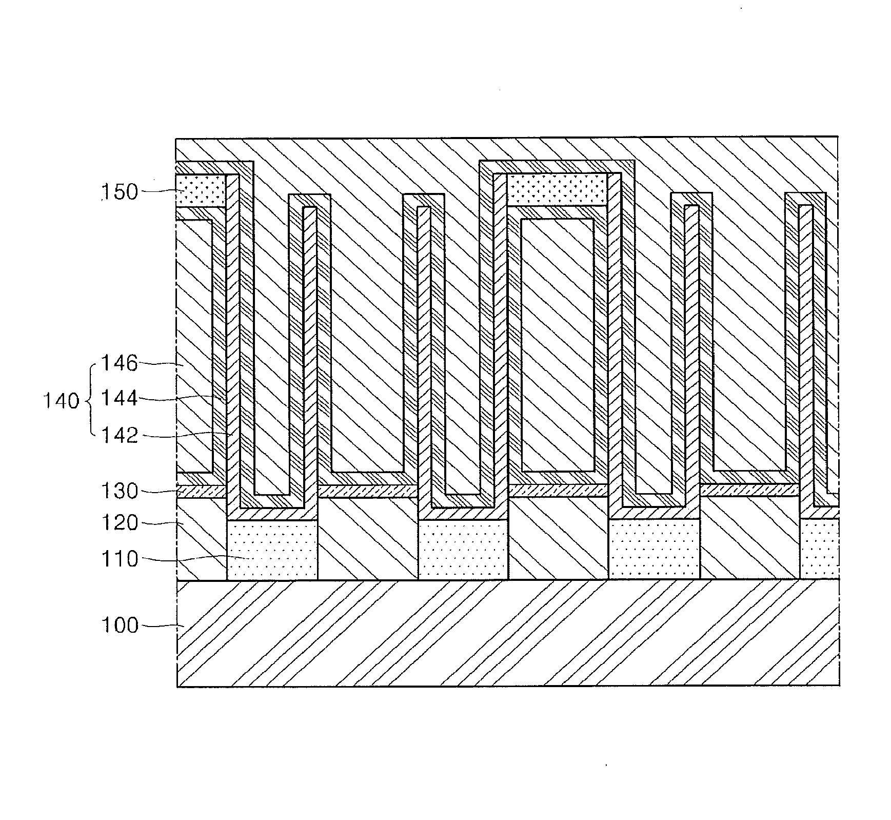
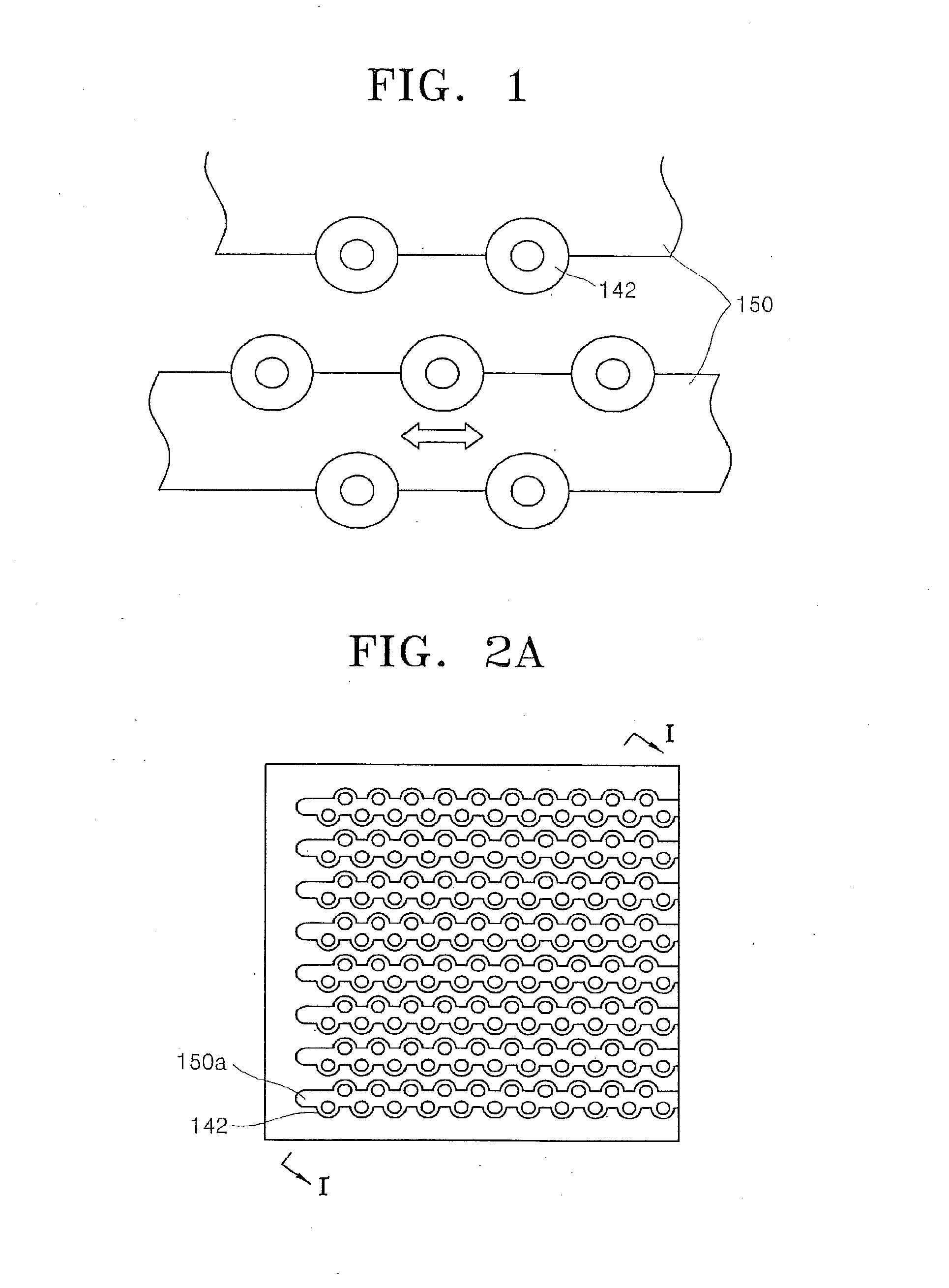
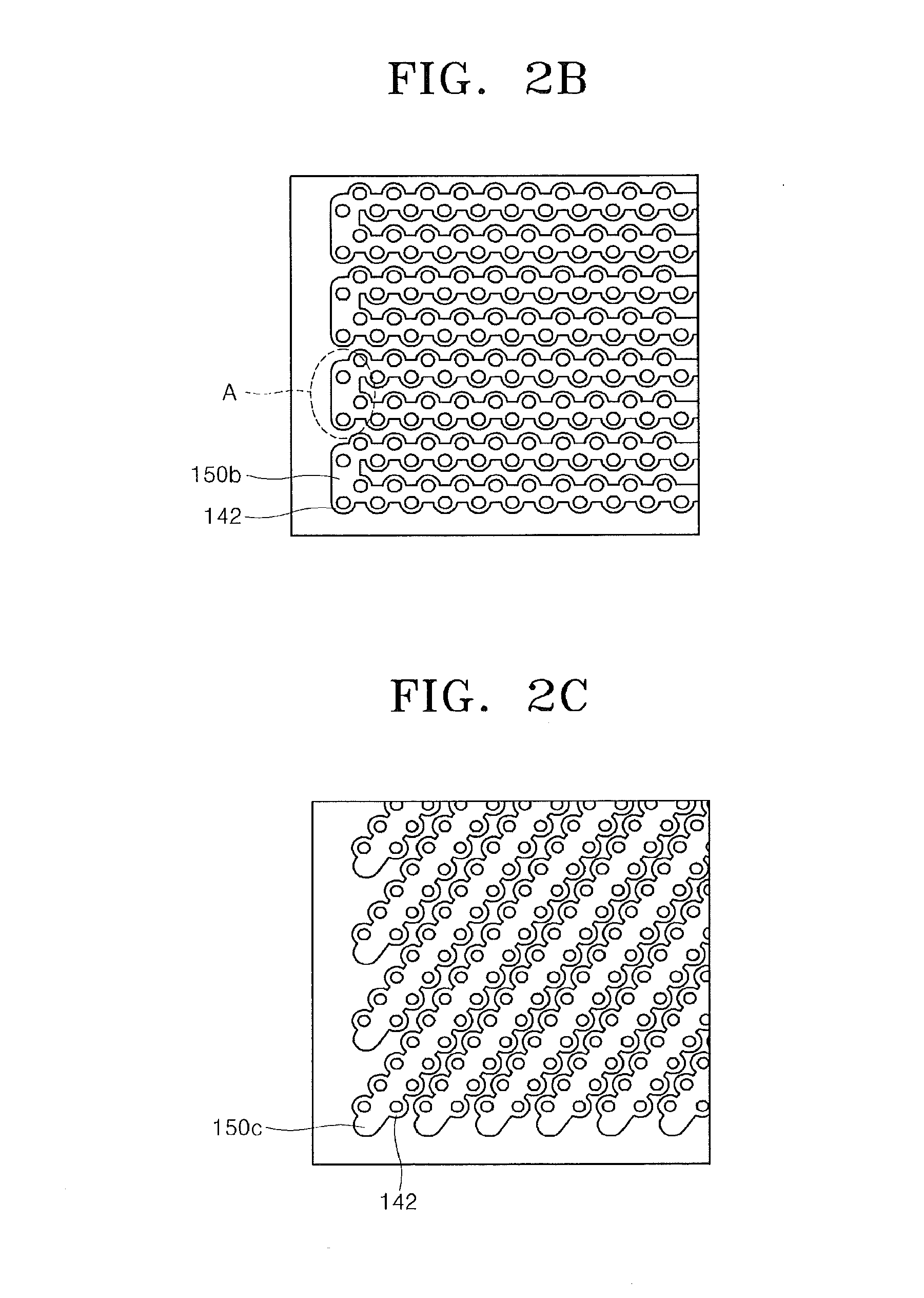
The present invention provides semiconductor devices including a capacitor with support pads. The support pads are formed in stripes between the lower electrodes to reduce stress and facilitate the deposition of subsequent materials. This results in improved electrical characteristics. Additionally, a space between the lower electrodes can be increased by removing the support pads, which allows for symmetrical and uniform deposition of a dielectric film.

Problems solved by technology

When growing HSGs on lower electrodes a critical dimension (CD) between the lower electrodes may be difficult to secure.
Because HSGs may be detached from the lower electrodes and may cause bridges between the lower electrodes, growing the HSGs may be difficult to apply to a semiconductor device having a design rule of 0.14 μm (micrometer) or less.
Thus, such electrodes may collapse or break before the deposition of a dielectric material.
One of the main reasons that lower electrodes may collapse is a surface tension of a cleaning liquid used in a cleaning liquid-drying process after wet etching of a mold oxide film.
Expansion of the area of an electrode by conventional methods may be limited due to collapsing of the lower electrodes, and a method of forming supporting pads has been devised to address this problem.
In addition, a material used in a subsequent process may not be symmetrically and uniformly deposited because the interval between the lower electrodes may be too narrow due to the lattice support pads.
Furthermore, the non-uniformly deposited subsequent materials may increase the stress applied to the lower electrodes.
Therefore, when the lower electrodes collapse, break, or are twisted due to the stress applied by the pads, bridges or leakages may be caused between cells, thereby causing defects in semiconductor devices.
Accordingly, a distribution of CMP slurry (quantity) on the water may deteriorate, and the thickness of the oxide film after the CMP process is performed may not be sufficiently uniform.
The non-uniform thickness of the oxide film may cause open CD distribution deterioration during an etch used to form subsequent metal plugs, thereby decreasing product yield.

Method used


Image

  • Semiconductor devices including capacitor support pads
  • Semiconductor devices including capacitor support pads
  • Semiconductor devices including capacitor support pads

Examples


Embodiment Construction

[0053]The present invention is described more fully hereinafter with reference to the accompanying drawings, in which embodiments of the present invention are shown. This invention may, however, be embodied in many different forms and should not be construed as limited to the embodiments set forth herein. Rather, these embodiments are provided so that this disclosure will be thorough and complete, and will fully convey the scope of the present invention to those skilled in the art. In the drawings, the sizes and relative sizes of layers and regions may be exaggerated for clarity. Like numbers refer to like elements throughout.

[0054]It will be understood that when an element or layer is referred to as being “on”, “connected to” or “coupled to” another element or layer, it can be directly on, connected or coupled to the other element, or layer or intervening elements or layers may be present. In contrast, when an element is referred to as being “directly on,”“directly connected to” or...


PUM


Abstract

A semiconductor device may include a semiconductor substrate and a plurality of first capacitor electrodes arranged in a plurality of parallel lines on the semiconductor substrate with each of the first capacitor electrodes extending away from the semiconductor substrate. A plurality of capacitor support pads may be provided with each capacitor support pad being connected to first capacitor electrodes of at least two adjacent parallel lines of the first capacitor electrodes and with adjacent capacitor support pads being spaced apart. A dielectric layer may be provided on each of the first capacitor electrodes, and a second capacitor electrode may be provided on the dielectric layer so that the dielectric layer is between the second capacitor electrode and each of the first capacitor electrodes. Related methods are also discussed.

Description

RELATED PATENT APPLICATION[0001]This application claims the benefit of priority as a continuation of U.S. application Ser. No. 12 / 137,634 filed Jun. 12, 2008, which claims the benefit of Korean Patent Application No. 10-2007-0057995, filed on Jun. 13, 2007, in the Korean Intellectual Property Office. The disclosures of both of the above referenced applications are incorporated herein in their entireties by reference.FIELD OF THE INVENTION[0002]The present invention relates to electronics, and more particularly, to a semiconductor device including capacitors and related methods.BACKGROUND[0003]As the area occupied by various semiconductor elements in semiconductor devices such as a dynamic random access memories (DRAMs) has been reduced by increased integration, a cell capacitance should be maintained constant or increased. Some methods used to ensure a sufficient cell capacitance within a limited area include using a high dielectric material as a dielectric film, reducing a thicknes...

Claims


Application Information

Patent Timeline
Patent Type & Authority Applications(United States)
IPC IPC(8): H01L49/02H10N97/00
CPCH01L28/40H01L27/0207H01L28/91H10B12/033H10B12/00
Inventor CHO, YOUNG-KYUIM, KI-VINCHOI, YONG-HEE
Owner SAMSUNG ELECTRONICS CO LTD
Learn More