
Apparatus for generating a multi-vibrational field

a technology of vibration field and apparatus, applied in the field of apparatus, can solve the problem that the electromagnetic field may not be suitable for use in other applications

Inactive Publication Date: 2013-11-07
WILSON GARY DEAN +1
View PDF2 Cites 3 Cited by
  • Summary
  • Abstract
  • Description
  • Claims
  • Application Information

AI Technical Summary

Benefits of technology

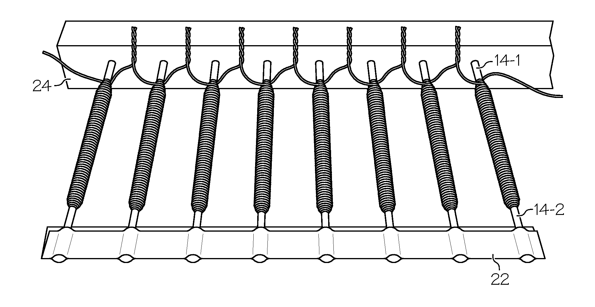
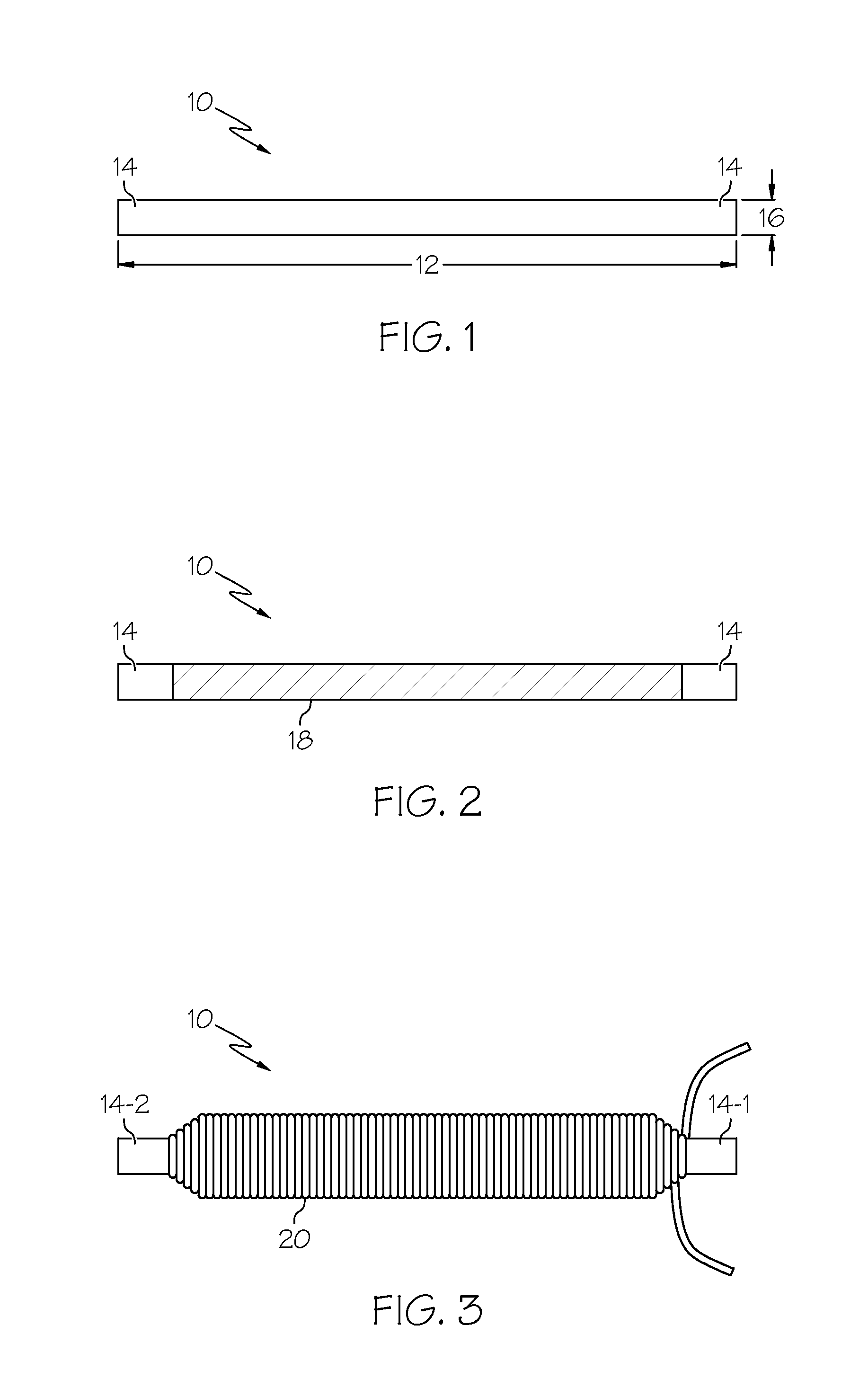
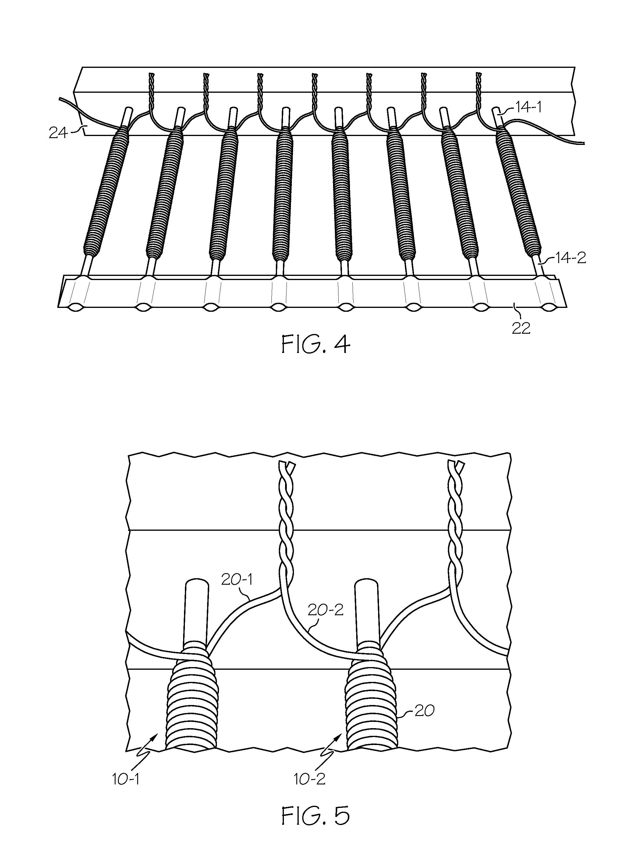
The present invention relates to an electromagnetic apparatus for generating a multi-vibrational electromagnetic field. The apparatus comprises a plurality of rods, each partially covered with a non-conductive coating leaving the opposing ends of the rods uncovered. Copper wire is wrapped around each of the rods, over the non-conductive coating, forming a plurality of copper coils connected in sequence to a power supply. The apparatus also includes a spacer strip attached to each end of the rods and a flexible housing for containing the copper coils. The technical effect of the invention is the ability to generate a multi-vibrational electromagnetic field with a compact and efficient design.

Problems solved by technology

Such an electromagnetic field may not be suitable for use in other applications, such as human therapeutic applications.

Method used


Image

  • Apparatus for generating a multi-vibrational field
  • Apparatus for generating a multi-vibrational field
  • Apparatus for generating a multi-vibrational field

Examples


example 1

Reduction of Nitrates / Nitrites

[0040]A manufacturer of health foods in Central Texas has a water softener and a reverse osmosis installed in their plant to remove hardness and nitrate / nitrites in the water. Nitrates / nitrites tested 1.0 ppm. A soft wave apparatus, according to an embodiment of the present invention, was installed to reduce salt usage and improve the efficiency of the reverse osmosis. The nitrate / nitrite levels tested zero after the installation of the soft wave apparatus.

example 2

Water Discoloration from Vegetation

[0041]Last summer on Father's Day weekend, a pool that had been opened for 6-7 weeks had cloudy water that the pool service company could not clear up. The pool company had closed / covered the pool (for winterizing) with a large amount of leaves at the bottom. A soft wave apparatus, according to an embodiment of the present invention, was installed on the pool. The installation was as described above and the cloudy water cleared up by the very next day. It was also noticed that the usual negative effects (dry skin and hair, burning eyes and chlorine order) of the chlorine were not present. Days later, the pool clarity kept increasing. The pool was about 35,000 gallons and included sand filtration and a gas heater. The pool water temperature is normally kept around 85 degrees.

example 3

Tannins Removed from Water

[0042]A home with a Culligan softener and a pool, all on well water, had a complaint of yellow water (lab analysis showed presence of tannins). Three soft wave apparatus, according to an embodiment of the present invention, were installed one on the well, one on the pool and one inline before the softener. Lab tested 0 tannins and TDS (Total Dissolved Solids) dropped 300 ppm from 1000 pmm. Home owner took pictures of their crystal blue pool (first time clear in 8 yrs).


PUM


Abstract

An apparatus may deliver multi-vibrational electromagnetic (MVEM) fields which are independent but may work simultaneously. The MVEM fields may be used in many applications, including eliminating calcium build-up in pipes, reducing soap usage in laundry, reducing salt usage in water softeners, reducing chlorine use in pools, inhibiting algae growth, increasing water clarity, restructuring or inhibiting nitrates, restructuring or inhibiting tannins, restructuring or inhibiting calcium salts and other minerals, treating pain, treating inflammation, enhancing after-surgery healing, and improving circulation in treated areas of animals and humans. The apparatus may be formed from a plurality of wire-wrapped rods connected to a power supply. The plurality of rods may be incased in flexible foam and wrapped in a fabric outer covering.

Description

CROSS-REFERENCE TO RELATED APPLICATIONS[0001]This application claims the benefit of U.S. Provisional patent application No. 61 / 164,549 filed Mar. 30, 2009.BACKGROUND OF THE INVENTION[0002]The present invention generally relates to electromagnetism and, more particularly, to an apparatus that may deliver electromagnetic multi-vibrations fields that are independent but work simultaneously.[0003]Magnetic fields have been used in various applications, such as therapeutic applications for treating the human body and water cleaning applications. A conventional electromagnetic water treatment apparatus may include an electric field and a magnetic field to prevent the occurrence and attachment of scale and rust along a channel used for the circulation of water. The presently available electromagnetic water treatment apparatus is so designed that a pair of permanent magnets and a pair of electrodes, composed of different metals, are attached to a casing, and along with the casing, collective...

Claims


Application Information

Patent Timeline
Patent Type & Authority Applications(United States)
IPC IPC(8): H01F3/10
CPCA61N1/40A61N2/008A61N2/02C02F1/005Y10T29/4902C02F2201/483C02F2303/22H01F3/10C02F1/48
Inventor WILSON, GARY DEANBROWN, MICHAEL DEAN
Owner WILSON GARY DEAN
Learn More