Multilayer inductor and method of manufacturing the same

a technology of inductance and multi-layer, applied in the direction of transformer/inductance details, inorganic material magnetism, etc., can solve the problems of increasing material loss, deterioration of high frequency characteristics in a product, and inability to implement the high current characteristics required for various electronic products, etc., to achieve high current and improve the effect of inductance valu

Inactive Publication Date: 2013-11-07
SAMSUNG ELECTRO MECHANICS CO LTD
View PDF3 Cites 49 Cited by
  • Summary
  • Abstract
  • Description
  • Claims
  • Application Information

AI Technical Summary

Benefits of technology

[0018]An aspect of the present invention provides a multilayer inductor able to maintain reliability at a predetermined level and improve an inductance value at high current.

Problems solved by technology

In the case of increasing the number of windings in order to obtain high levels of inductance and capacitance, stray capacitance between the coils, that is, capacitance between conducting wires, may be generated, such that high frequency characteristics in a product may be deteriorated.
However, since the ferrite material has a saturation magnetization value lower than that of metal, high current characteristics required for various electronic products may not be implemented.
However, in this case, eddy current loss and hysteresis loss at a high frequency may be increased, such that loss in the material may grow increasingly worse.
However, since a volume fraction of the metal is decreased, an effect of increasing the saturation magnetization value, an advantage of metal as described above, may not be appropriately implemented.

Method used


Image

  • Multilayer inductor and method of manufacturing the same
  • Multilayer inductor and method of manufacturing the same
  • Multilayer inductor and method of manufacturing the same

Examples


Embodiment Construction

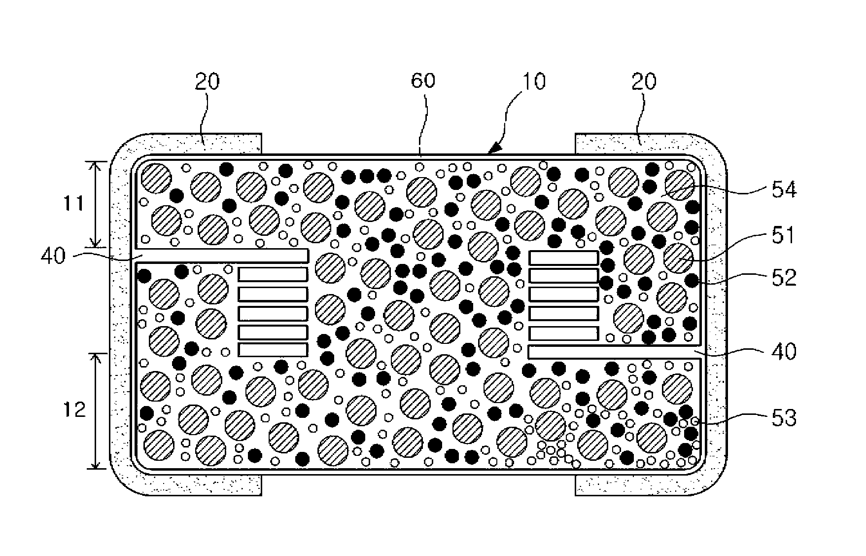
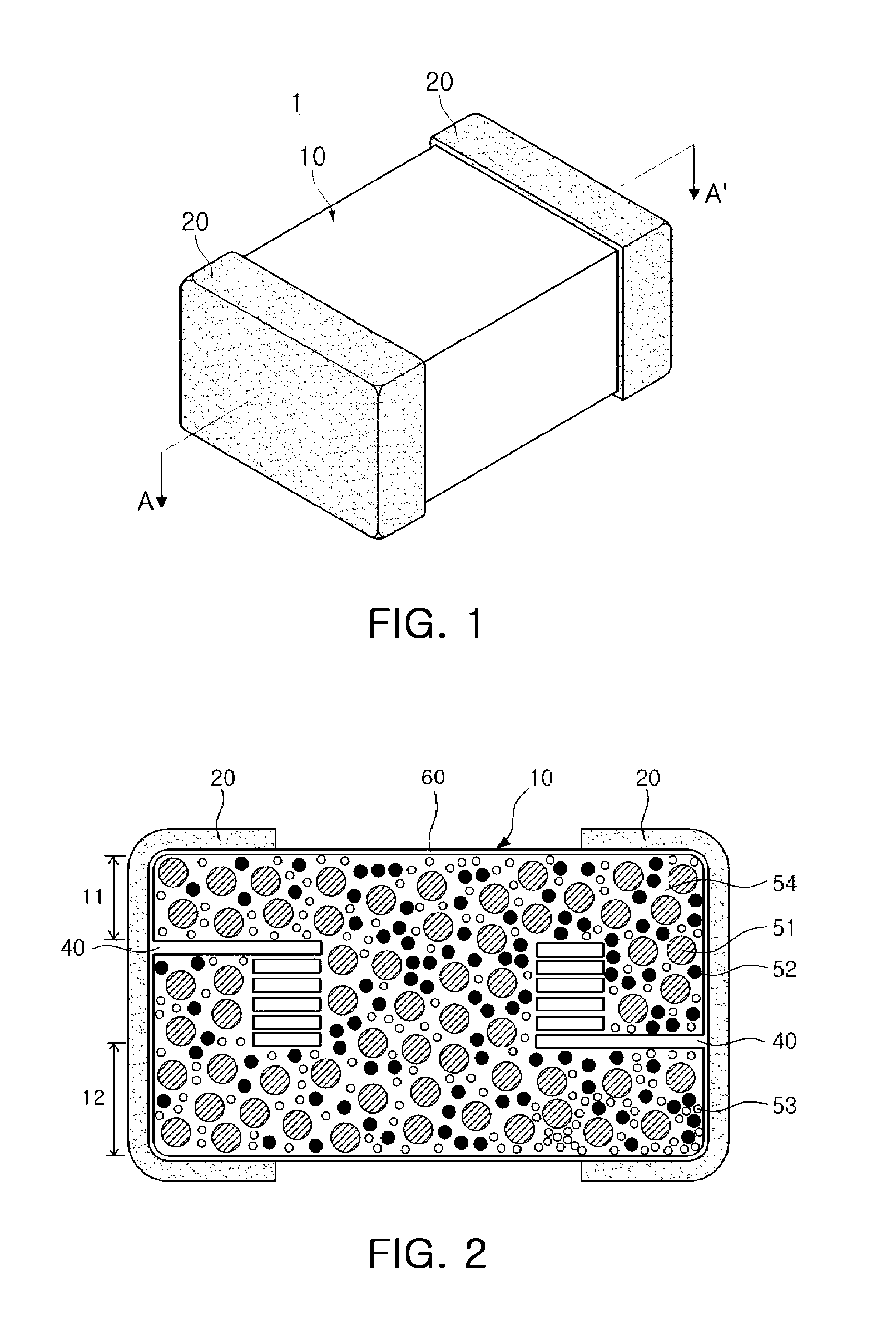
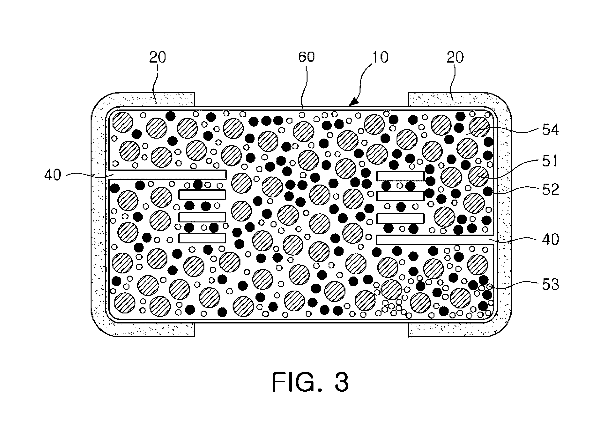
[0040]Hereinafter, embodiments of the present invention will be described in detail with reference to the accompanying drawings so that those skilled in the art may easily practice the present invention.

[0041]The invention may, however, be embodied in many different forms and should not be construed as being limited to the embodiments set forth herein.

[0042]Rather, these embodiments are provided so that this disclosure will be thorough and complete, and will fully convey the concept of the invention to those skilled in the art.

[0043]Therefore, in the drawings, the shapes and dimensions of elements may be exaggerated for clarity, and the same reference numerals will be used throughout to designate the same or like elements.

[0044]In addition, like reference numerals denote parts performing similar functions and actions throughout the drawings.

[0045]Unless explicitly described to the contrary, the word “comprise” and variations such as “comprises” or “comprising,” will be understood to...


PUM

PropertyMeasurementUnit
particle sizeaaaaaaaaaa
sizesaaaaaaaaaa
sizesaaaaaaaaaa

Abstract

There is provided a multilayer inductor including: an inductor body formed of a material including metal powder particles, a ferrite, and a polymer resin; a coil part having a conductive circuit and a conductive via formed in the inductor body; and external electrodes formed on ends of the inductor body.

Description

CROSS-REFERENCE TO RELATED APPLICATIONS[0001]This application claims the priority of Korean Patent Application No. 10-2012-0046562 filed on May 2, 2012, in the Korean Intellectual Property Office, the disclosure of which is incorporated herein by reference.BACKGROUND OF THE INVENTION[0002]1. Field of the Invention[0003]The present invention relates to a multilayer inductor and a method of manufacturing the same.[0004]2. Description of the Related Art[0005]Provided as representative electronic components using a ceramic material are a capacitor, an inductor, a piezoelectric element, a varistor, a thermistor, and the like.[0006]Among these ceramic electronic components, an inductor, as well as a resistor and a capacitor, is a main passive element constituting an electronic circuit, and may serve to remove noise or constitute an inductor-capacitor (LC) resonance circuit.[0007]The inductor may be manufactured by winding or printing a coil on a ferrite core and forming electrodes at both...

Claims


Application Information

Patent Timeline
Patent Type & Authority Applications(United States)
IPC IPC(8): H01F27/29
CPCH01F1/26H01F1/37H01F17/0033H01F27/292H01F41/046
Inventor SHIN, SUNG SIK
Owner SAMSUNG ELECTRO MECHANICS CO LTD
Why Eureka
Try Eureka