Device combining a thermal fuse and a resistor

a technology of resistor and thermal fuse, which is applied in the field of resistor, can solve the problems of rapid rise of thermal fuse temperature, and achieve the effects of increasing the resistor value, improving the stability of the resistor value of the resistor, and reducing the heating temperature of the resistor

Active Publication Date: 2013-11-07
XIAMEN SET ELECTRONICS +1
View PDF12 Cites 9 Cited by
  • Summary
  • Abstract
  • Description
  • Claims
  • Application Information

AI Technical Summary

Benefits of technology

[0010]The resistor value of the wirewound resistor with above structure is set in 0.5Ω, the temperature of the coupling thermal fuse is 150° C. used in a motor of a power tool, take a thermal fuse with rated current 2 A for example, when the normal working current is 0.5 A, the temperature of the thermal fuse rises about 5° C. due to the resistor. But when the motor is blocked, the current reaches to 3 A, the heat of the resistor makes the temperature of the thermal fuse rising rapidly, the thermal fuse is cut off before the motor coil is damaged. According to above structure, replace the wirewound resistor to a carbon-film resistor or a metal-film resistor, the resistor value is increased greatly, this structure can be used as a micro-heater, fix it into a ceramic tube to sever as a heater of a fragrance device or liquid electric mat, the heater can be placed in the diffusion staff of perfume or other liquid, so that the thermal power of the heater can be absorbed by the perfume or other liquid. Existing technology is applied with a ceramic structure, one side of which is disposed with a hole to fix the diffusion staff while the other side is disposed with a cavity, the cavity is assembled with a heating resistor and a thermal fuse and encapsulated by solidifiable insulation material. Comparing above two, basic on same diffusion rate of the perfume, the power of the existing technology of the heater is about 2.2 W, the power of the heater of the present invention is about 1 W, so that the heating temperature of the resistor is decreased, the stability of the resistor value of the resistor is improved greatly and the diffusion rate of the perfume is more stable, the influence from the environmental temperature is decreased. If the power of a fragrance device decreases 1 W, 9 kW power can be saved every year. If there are 50 millions heaters of fragrance device or liquid electric mat working in the world, 45000 kW power can be saved, carbon emission decreased greatly.

Problems solved by technology

But when the motor is blocked, the current reaches to 3 A, the heat of the resistor makes the temperature of the thermal fuse rising rapidly, the thermal fuse is cut off before the motor coil is damaged.

Method used


Image

  • Device combining a thermal fuse and a resistor
  • Device combining a thermal fuse and a resistor
  • Device combining a thermal fuse and a resistor

Examples


first embodiment

The First Embodiment

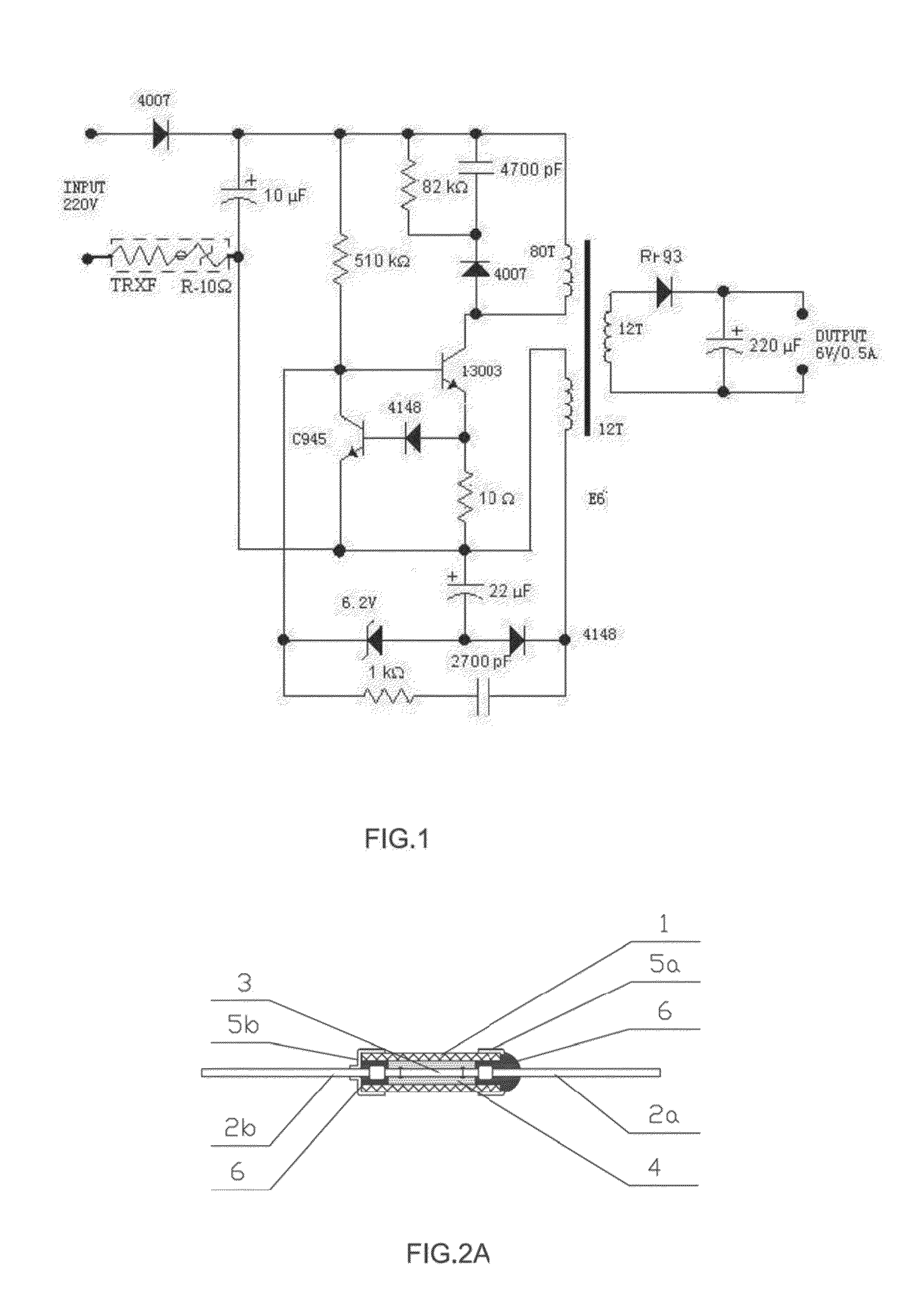
[0021]The first embodiment will be further described with the FIG. 1, FIG. 2A and FIG. 3A. thereinto, the object of the embodiment is to describe the preferred embodiment of the present invention, but not limited.

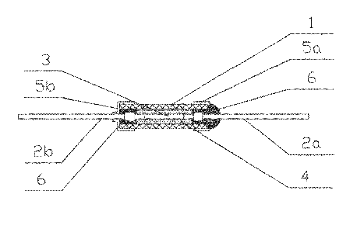
[0022]FIG. 1 is the circuit of a switched power supply charger of a mobilephone or an MP3, and the circuit is applied with the device combining a thermal fuse and a resistor of the present invention; in FIG. 2A, the lead wires 2b, 2a of the thermal fuse is welded with low-melting point alloy wire 3. A fluxing agent 4 is disposed around the alloy wire 3 to improve the alloy wire to contract to two sides and cut off when molten, the thermal fuse, fluxing agent 4 and the alloy wire 3 form a whole under the normal temperature to be placed inside the ceramic tube, then two ends of the ceramic tube are encapsulated by epoxy resin 6 to be made into an entire thermal fuse.

[0023]As figured in FIG. 2A, when above thermal fuse is formed, put the metal caps 5a, 5b t...

second embodiment

The Second Embodiment

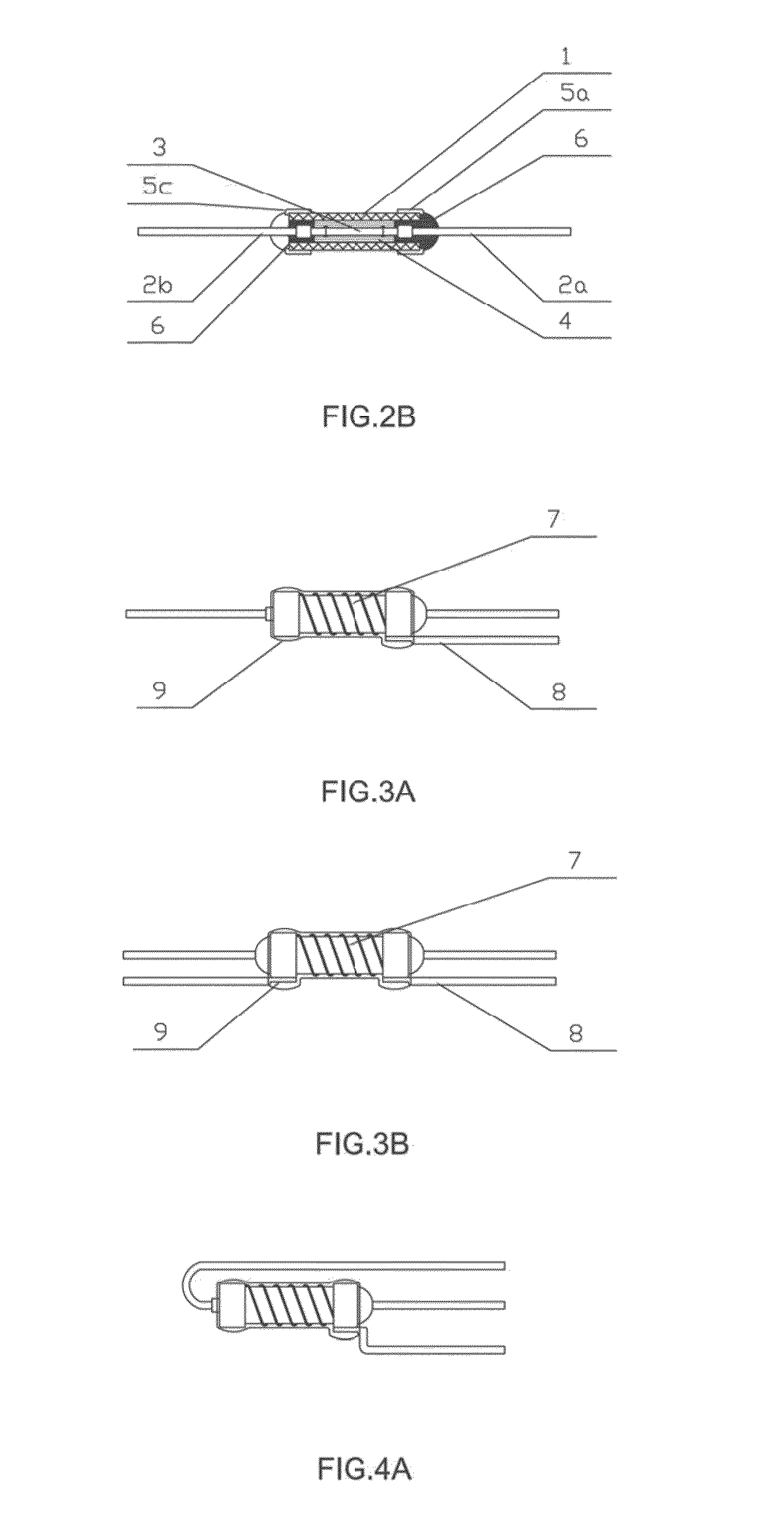
[0026]As figured in FIG. 2B and FIG. 3B, different from the first embodiment, the thermal fuse and the wirewound resistor are connected in parallel in a circuit, the wirewound resistor is wound to the ceramic housing of the thermal fuse. The lead wires of the metal caps (5a, 5c) in two ends of the wirewound resistor are not connected to the lead wires of the thermal fuse.

third embodiment

The Third Embodiment

[0027]The table below is the protection result data of the wirewound resistor with a thermal fuse in the first embodiment. In a high-frequency power supply, it often applies a 10Ω / 2 W wirewound resistor and a 221° C. thermal fuse against over-heat, the comparison of cut-off speed of the external contact type and the built-in type (the first embodiment) is as below. If single wirewound resistor is not added, high surface temperature for a long time is a hidden danger in the current in the table.

TABLE 1SurfaceSurfaceCut-off Time ofTemperature ofCut-off Time ofTemperature of thethe Externalthe Built-inthe Built-inTestExternal ContactContact TypeTypeType ThermalNumberCurrent AType Resistor ° C.Thermal Fuse SResistor ° C.Fuse S10.5142Not Cut-off in145Not Cut-off in600 s600 s20.5139Not Cut-off in142Not Cut-off in601 s601 s30.5146Not Cut-off in148Not Cut-off in602 s602 s40.5143Not Cut-off in145Not Cut-off in603 s603 s50.617536 s17618 s60.617437 s17719 s70.617836 s17618 ...


PUM


Abstract

A device combining a thermal fuse and a resistor has a solid ceramic base of the wirewound resistor is changed to be hollow, a thermal fuse is disposed inside the ceramic base, the ceramic tube is the housing of the thermal fuse, one lead wire of the thermal fuse is passing through the end cap of one end of the wirewound resistor, the other end of the thermal fuse is extended out of the end cap of the other end of the wirewound resistor, the end cap of the wirewound resistor is extended out with a lead wire, then the whole product is encapsulated by epoxy resin. The device can serve as a basic unit, which is directly assembled to an existing high-frequency charger, it can take the place of the existing simple wirewound resistor or the wirewound resistor with a thermal fuse external contacted.

Description

FIELD OF THE INVENTION[0001]The present invention relates to a resistor against over-current and over-heat, the device is a quick response structure with a resistor and a thermal fuse integration, the size is similar to a same power wirewound resistor, carbon-film resistor or a metal-film resistor, it's applied to over-heat resistor of the power supply of the household electric appliance, IT communication equipment or lighting equipment, it can be also be served as a heating element with over-heat protection.[0002]The present invention further relates to a thermal fuse with heating function, it can be applied in blockage protection of the motor of the power tool or electrical fan; when the motor is blocked, with the current, the increasing rate of the temperature of the thermal fuse to cut off is much larger than that of the temperature of the coil of the motor, assuring that the motor will not be over-heat and blocked before the cut-off of the thermal fuse, it can be used to agains...

Claims


Application Information

Patent Timeline
Patent Type & Authority Applications(United States)
IPC IPC(8): H01C13/00H01C3/20
CPCH01C13/00H01C3/20H01C1/08H01C1/14H01H37/761H01H85/0241H01H85/165H05B1/0205H01H85/0052
Inventor XU, ZHONGHOUXU, YOUSHENGZHU, XUANHUI
Owner XIAMEN SET ELECTRONICS
Why Eureka
Try Eureka