Method of treating radioactive metal waste using melt decontamination

a radioactive metal and melt decontamination technology, applied in the direction of radioactive decontamination, chemistry apparatus and processes, nuclear engineering, etc., can solve the problems of large amount of radioactive waste generated, radiation products, environmental protection and economic efficiency loss, etc., and achieve the effect of improving quality

Active Publication Date: 2013-11-07
KEPCO NUCLEAR FUEL CO LTD
View PDF0 Cites 7 Cited by
  • Summary
  • Abstract
  • Description
  • Claims
  • Application Information

AI Technical Summary

Benefits of technology

The invention provides a method for treating waste containing radioactive metals by using a process called melt decontamination. The waste is first classified based on its generation source and material quality. Then, surface decontamination is carried out as a pretreatment step based on the level of radioactivity. This improves the quality of the final ingot produced.

Problems solved by technology

Generally, there are various types of radioactive waste generated from nuclear power plants, nuclear research institutes and the like, such as metals, concretes, contaminated oil and the like occurring when maintaining and dismantling nuclear facilities, and a large amount of this waste is generated.
For this reason, when radioactive metal waste is discarded and not recycled, there may be a great loss in terms of environmental protection and economic efficiency.
However, radiation products are problematic in that they cannot be removed just by surface decontamination because they are distributed even in the metal matrix, and in that their surface contamination cannot be measured because metal products having a complicated geometric shape, such as bolts or nuts, are difficult to treat using surface decontamination and they have a planar area smaller than the effective area of a measuring instrument.
Meanwhile, conventional surface decontamination for treating radioactive metal waste is problematic in that metal contaminants having a complicated geometric shape cannot be removed, and in that contaminants distributed in the matrix of metal as well as on the surface of metal cannot be removed.

Method used


Image

  • Method of treating radioactive metal waste using melt decontamination
  • Method of treating radioactive metal waste using melt decontamination
  • Method of treating radioactive metal waste using melt decontamination

Examples


example 1

Preparations for Test

[0050](1) Test Summary

[0051]In order to estimate the material balance attributable to the melt decontamination of the present invention, 1 kg of UO2 having a concentration of 4.65 w / o was charged in a non-contaminated metal material, and one sample was extracted from a molten solution and then the gamma nuclide analysis of the one sample was conducted using ICP-MS (inductively coupled plasma mass spectroscopy) and a high-purity germanium (HPGe) detector. Then, two ingots were selected from the produced ingots, samples were extracted from nine portions per single ingot, and then the uranium concentration of each of the samples was analyzed using ICP-MS to prove the homogeneity of the molten solution. Further, gamma nuclide analysis of the slag occurring during the melt decontamination was carried out using a high-purity germanium (HPGe) detector and the ICP-MS analysis thereof were simultaneously conducted to grasp the decontamination coefficient and estimate the...

example 2

Performance of Melt Decontamination

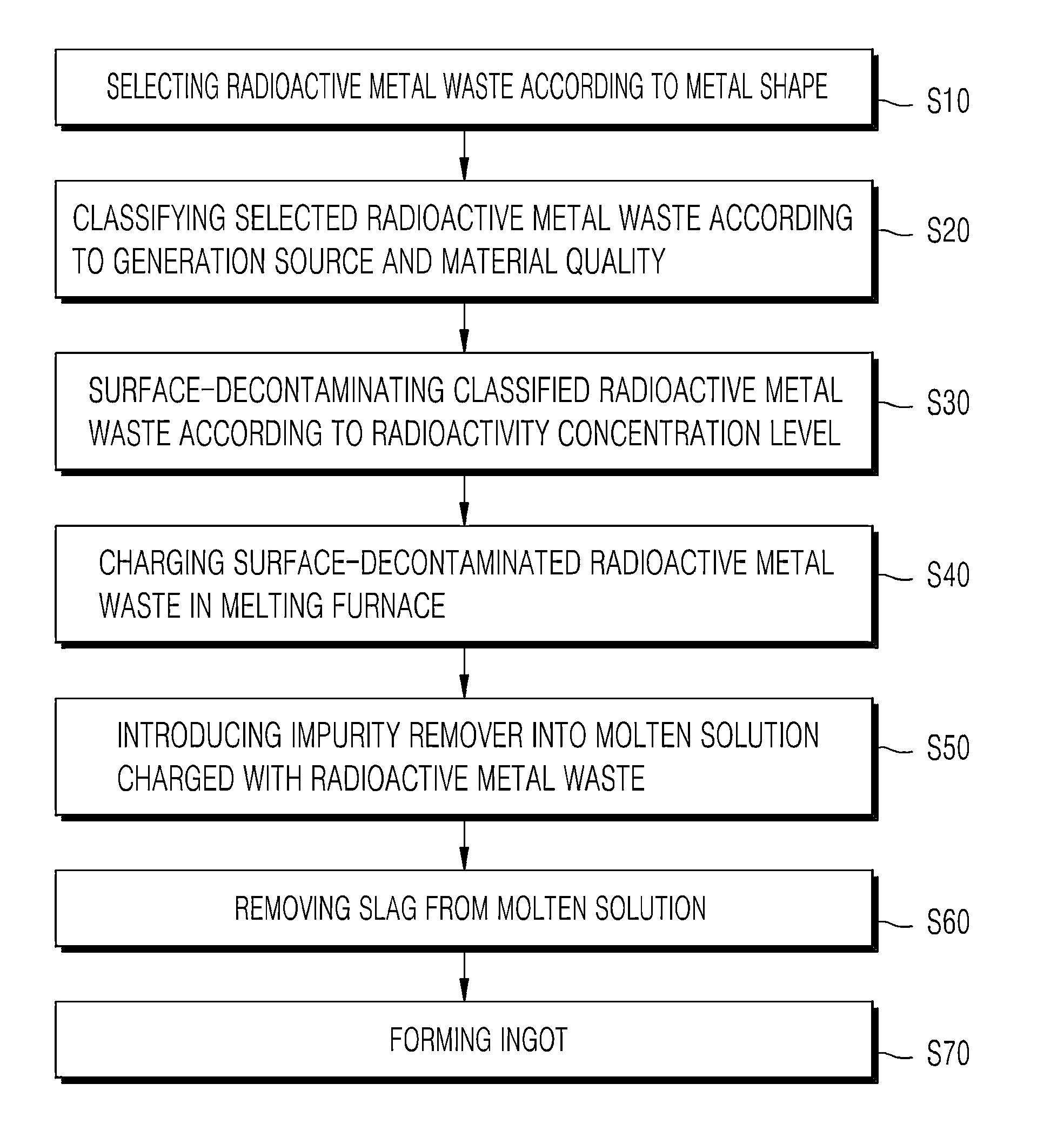
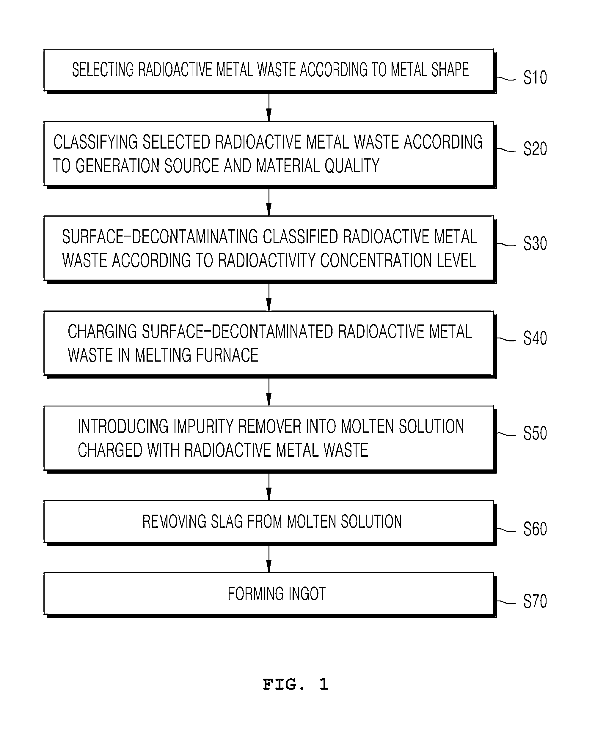
[0055]The melt decontamination test was conducted for about 3 hours according to the following processes. Further, the work of separating the ingot from a mold was conducted the day after the melt decontamination test because this work must be conducted in a state in which the ingot has sufficiently cooled. The melt decontamination process according to the present invention is shown in FIG. 1, and the melt decontamination process according to Example 1 will be described in detail as follows.

[0056]In the process of selecting metal waste, the metal waste generated from nuclear fuel processing facilities is considered to be a material contaminated by radioactive material. Here, flat metal waste having a simple and smooth geometric shape such as filter frames, waste drums and the like; and metal waste, such as nuts, bolts and the like, which cannot be easily surface-decontaminated by conventional methods because they have a complicated geometric shape,...

example 3

Sample Extraction

[0061]Samples were extracted from the ingot and slag produced in the process of conducting melt decontamination according to Example 2 of the present invention, and the extraction of the samples was carried out according to ASTM-1806.

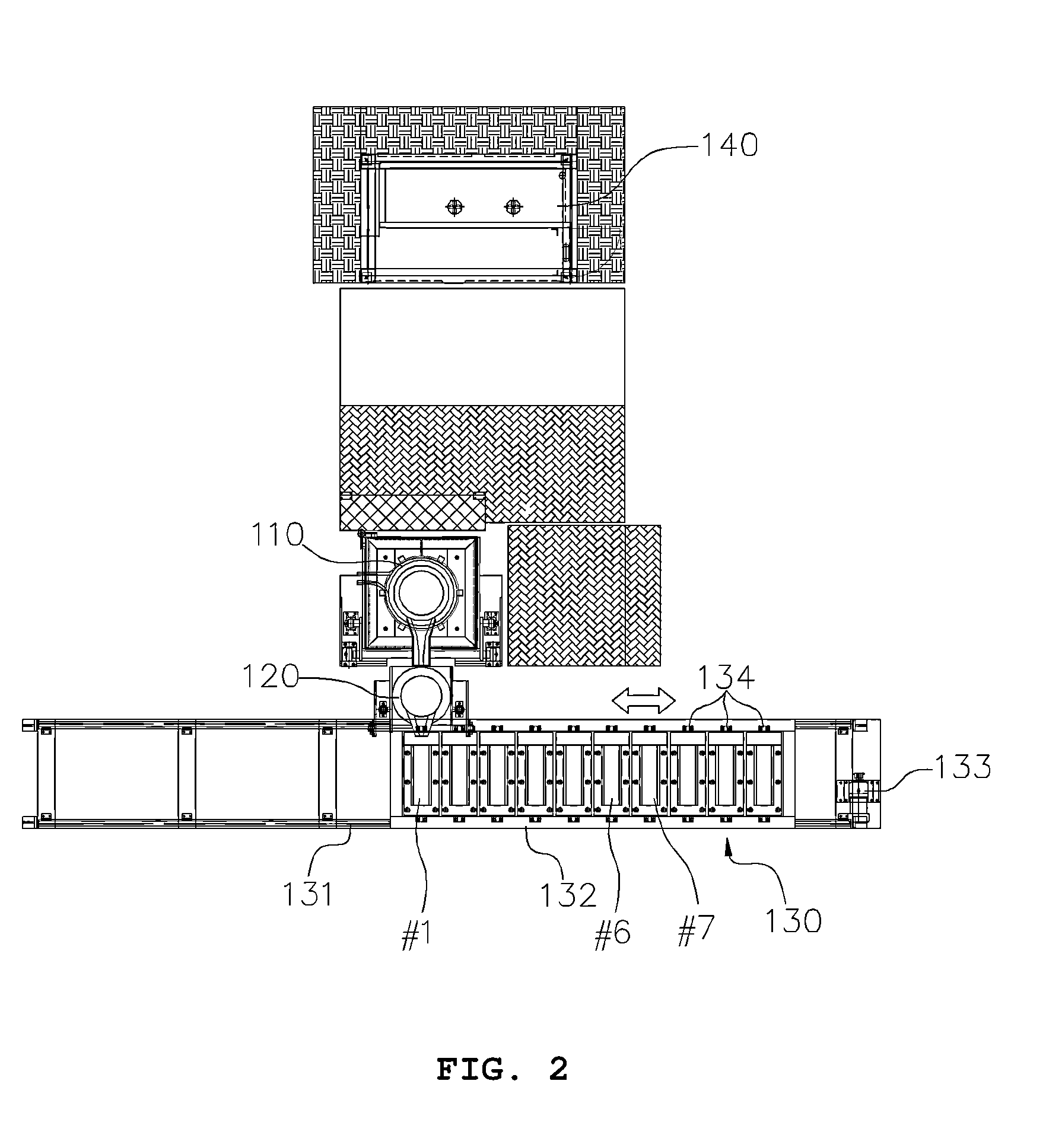
[0062]The results of analyzing the extracted samples are given in Table 1. Meanwhile, among ten ingots melt-decontaminated according to Example 1, the ingots fabricated in the first mold, the sixth mold and the seventh mold are represented by #1, #6 and #7, respectively (refer to FIG. 2).

TABLE 1SampleGamma extractionnuclideICP-MSClassificationsmethodanalysisanalysisRemarks#3 ingot (23.6 kg)milling1000 mL1 EA#6 ingot (36.6 kg)drilling3 × 3 EA#7 ingot (22.4 kg)drilling3 × 3 EAMolten solutionmilling1000 mL1 EAcrucible(6.4 kg)typeSlag (—)—3 EASumabout 2000 mL23 EA

[0063]As given in Table 1 above, among the ten ingots produced according to Example 2, three ingots were selected (refer to FIG. 2), and nine samples were extracted from each of th...


PUM


Abstract

Disclosed herein is a method of treating radioactive metal waste using melt decontamination, wherein radioactive metal waste, which is generated from nuclear fuel processing facilities or nuclear fuel production facilities, and which cannot be easily treated by surface decontamination because it has a complicated geometric shape, and the surface contamination of which cannot be measured, can be treated by melt decontamination. The method is advantageous in that radioactive metal waste, which cannot be treated by conventional surface decontamination, can be treated, so that radioactive metal waste can be recycled, thereby obtaining economic profits, and further in that a large storage space necessary for cutting and then storing radioactive metal waste is not required, and in that excessive manpower and cost are not required.

Description

BACKGROUND OF THE INVENTION[0001]1. Technical Field[0002]The present invention relates to a method of treating radioactive metal waste using melt decontamination, and, more particularly, to a method of treating radioactive metal waste using melt decontamination, wherein radioactive metal waste, which is generated from nuclear fuel processing facilities or nuclear fuel production facilities, which cannot be easily treated by surface decontamination because it has a complicated geometric shape, and the surface contamination of which cannot be measured, can be treated by melt decontamination.[0003]2. Description of the Related Art[0004]Generally, there are various types of radioactive waste generated from nuclear power plants, nuclear research institutes and the like, such as metals, concretes, contaminated oil and the like occurring when maintaining and dismantling nuclear facilities, and a large amount of this waste is generated.[0005]Among the various types of radioactive waste, the...

Claims


Application Information

Patent Timeline
IPC IPC(8): G21F9/30
CPCG21F9/308G21F9/301G21F9/34Y10S588/901G21F9/30
Inventor CHO, SUK JULEE, YOUNG BAESEOL, JEUNG GUNKIM, YONG JAEHAN, WOOK JINRYU, JAE BONGKANG, HYUN GYU
Owner KEPCO NUCLEAR FUEL CO LTD
Why Eureka
Try Eureka