Eureka AIR delivers breakthrough ideas for toughest innovation challenges, trusted by R&D personnel around the world.

Control apparatus, control method and storage medium

a control apparatus and control method technology, applied in the field of control apparatus and control methods, can solve the problems of high cost of mechanisms, high processing costs, and rapid growth of processing targets

Active Publication Date: 2013-11-07
CANON KK
View PDF10 Cites 25 Cited by
  • Summary
  • Abstract
  • Description
  • Claims
  • Application Information

AI Technical Summary

Benefits of technology

The present invention provides a control apparatus and method that can detect a control signal for a movable device and select the most suitable transmitter station to transmit data to the movable portion multiple times based on the control signal. This results in more efficient and effective control over the device.

Problems solved by technology

For example, in precision machining applications, the expansion and contraction of processing targets, end effector components, and so on due to heat can quickly become problematic; thus such processors are often disposed in locations distanced from the robot, and remotely control the robot using a communication cable.
Such mechanisms have high costs, and also carry a risk of degradation and disconnection due to the cable repeatedly deforming; there is consequently an increased need to control end effectors through wireless communication.
However, wireless communication techniques widely used in the field of mobile information terminals, such as wireless LAN (local area network) and the like, are generally difficult to employ in the aforementioned applications.
Wireless LAN and the like were not designed with such applications in mind, and thus do not meet the demands of industrial devices.
However, even in the case where it is necessary to transmit uncompressed image data but it is not necessary to transmit control data at low latency, there are cases, due to issues such as device size and heat, where it is difficult to use separate communication systems, such as using millimeter wave communication to transmit image data and wireless LAN to transmit control data.
It is typically more difficult to ensure reliability in wireless communication than in wired communication.
One reason for this is that wireless communication is susceptible to shielding of and reflections from obstacles, noise from surrounding sources, and so on.
End effectors not only constantly change position, orientation, and so on as the arm moves, but also operate in environments where other apparatuses are moving in the periphery, and thus ensuring reliability when employing wireless communication to control robots is an issue.
High-frequency electromagnetic waves such as millimeter waves, submillimeter waves, and so on have a high degree of straightness, and have a property in which communication is difficult, even at short distances, in a non line-of-sight environment.
Meanwhile, even if the line-of-sight can be ensured, there are cases where communication fails due to reflections from nearby objects, noise, and so on.
However, with conventional techniques, it has not been possible to automatically perform such communication control in accordance with arm operations.
As a result, there has been a problem in that in some cases, the communication reliability necessary for robot control cannot be ensured, and it is thus necessary to carry out hard-wired control, incurring high costs as a result.

Method used


Image

  • Control apparatus, control method and storage medium
  • Control apparatus, control method and storage medium
  • Control apparatus, control method and storage medium

Examples


first embodiment

System Configuration

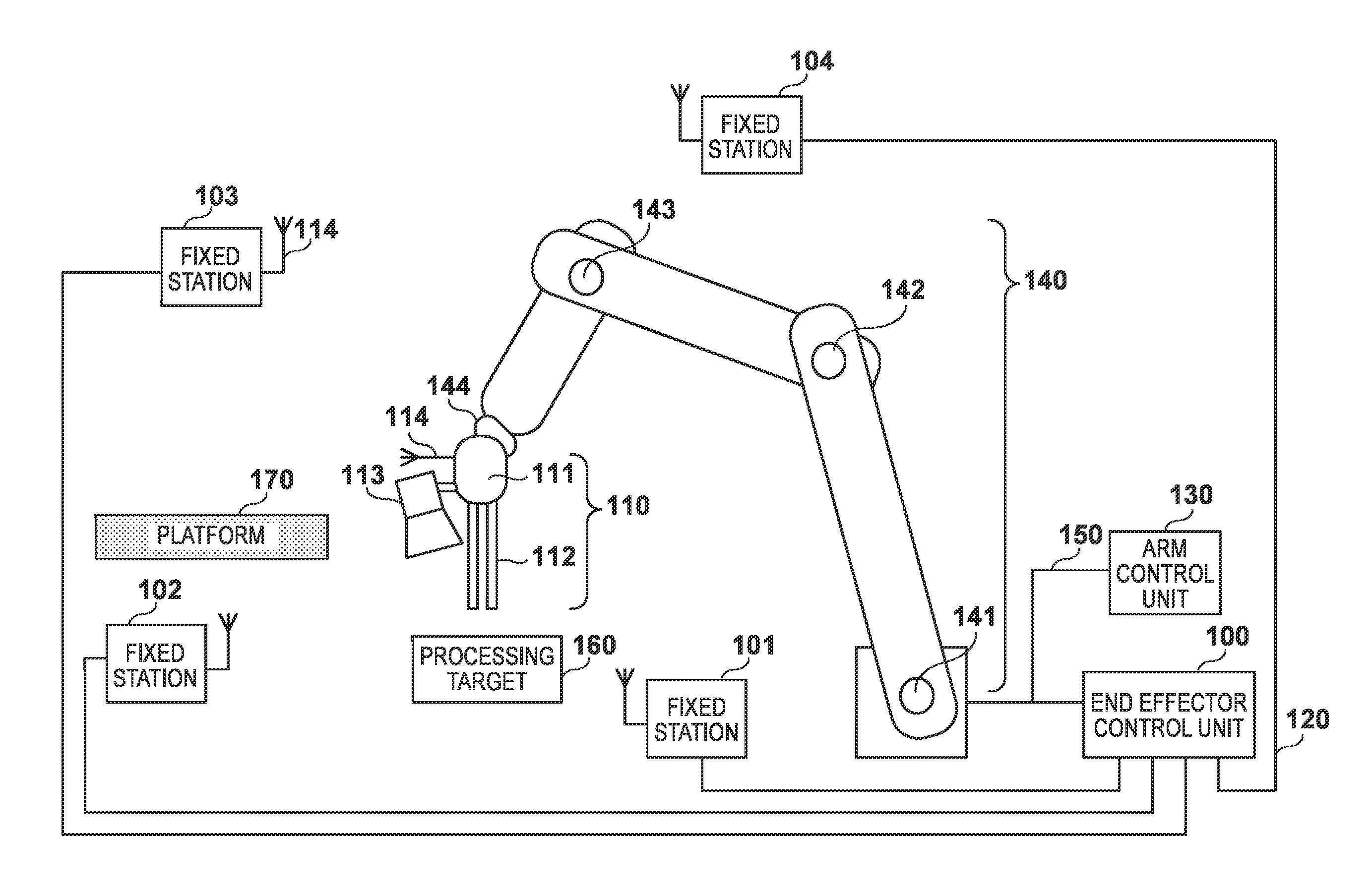
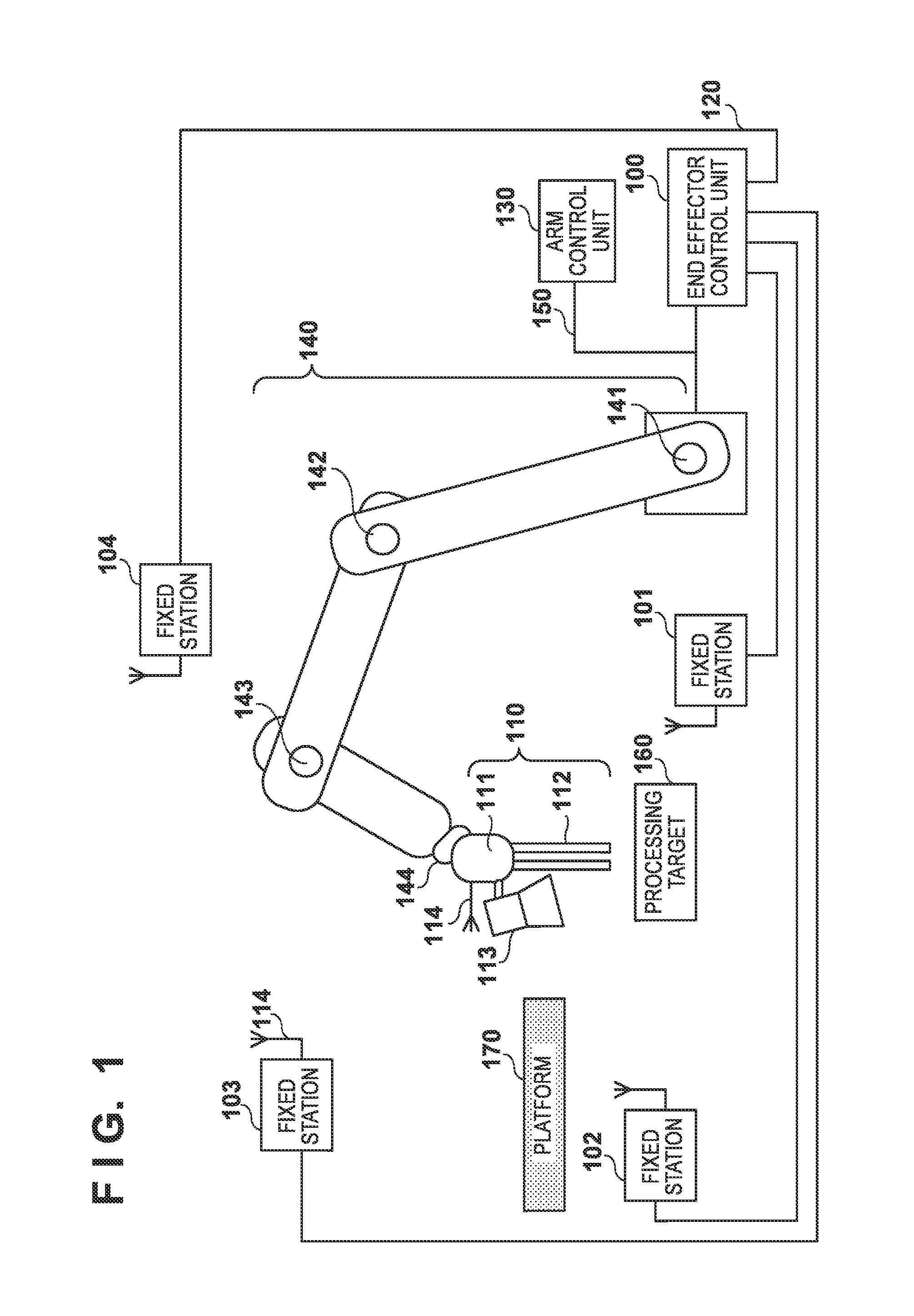
[0029]FIG. 1 is a diagram illustrating an example of the overall configuration of a system that includes a communication system according to the present embodiment. This system uses a device (a robot) including an end effector 110 and an arm 140 to perform a predetermined process on a processing target 160 and place the processing target 160 that has been processed onto a platform 170. The arm 140 includes movable portions (joints), and is capable of changing the location, orientation, and so on of the end effector 110. The end effector 110 includes, for example, a movable station 111, a pincher hand 112, and a camera 113. The movable station 111 is a communication device for performing wireless communication. The pincher hand 112 operates on the processing target 160, and the camera 113 captures that operation.

[0030]The system further includes an end effector control unit 100, fixed stations 101 to 104, and an arm control unit 130. The end effector control unit ...

second embodiment

[0062]The present embodiment will describe a system in which the arm 140 illustrated in FIG. 1 operates according to a predefined sequence. With this system, the content of the arm control signal output from the arm control unit 130 changes in the same manner with each sequence of operations. In the field of industrial devices, such cases in which the arm performs the same operations every time are comparatively numerous. In the present embodiment, this property will be used to achieve the same effects as those of the first embodiment, with a simpler configuration. The following will describe areas that are different from the first embodiment.

[0063]The arm control information detection unit 402 counts the number of times the arm control signal has been detected on the bus 150, and communicates the count value to the communication control unit 401. In the case where the power being turned on has been detected, the case where a predetermined arm control signal has been detected on the...

third embodiment

[0073]The present embodiment obtains an even better spatial diversity effect by preventing the end effector control frame from being sequentially transmitted from the same fixed station when transmitting a plurality of times from a fixed station whose communication quality is predicted to be good. The following will describe areas that are different from the first embodiment.

[0074]In S808 of FIG. 8, the communication control unit 401 selects, based on the algorithm illustrated in FIG. 11, another single fixed station whose predicted communication quality is 1. The processing illustrated in FIG. 11 is started as a result of the process of S808 in FIG. 8 being started. The communication control unit 401 defines a variable X, and substitutes ((i+[N / 2])mod N) for X (S1101). Here, the value i is i at the point in time when the process of S808 in FIG. 8 is started. N, meanwhile, expresses the total number of fixed stations. mod represents a modulo operation, and thus (A mod B) represents ...


PUM


Abstract

A control apparatus detects a control signal that controls a movable portion of a device, and selects, from a plurality of transmitter stations, a transmitter station that transmits data a plurality of times to a movable station moving in accordance with movement of the movable portion, based on the detected control signal.

Description

BACKGROUND OF THE INVENTION[0001]1. Field of the Invention[0002]The present invention relates to techniques for controlling communication between a movable station that is provided in a device and that moves and a fixed station.[0003]2. Description of the Related Art[0004]In the field of industrial devices, the development of cell-production robots, in which a single robot is capable of performing multiple types of operations, has been advancing. Such robots are comprised of an arm that is used for all tasks and an end effector that corresponds to an area from the wrist down. Multiple types of end effectors are prepared based on the type of each task, and the robot automatically exchanges end effectors depending on the type of the task, such as welding, gripping, tightening screws, and so on. There are some end effectors capable of executing advanced processes, such as capturing a processing target using a mounted camera, performing image processing on the captured image, and select...

Claims


Application Information

Patent Timeline
IPC IPC(8): B25J9/16
CPCB25J9/16B25J13/006H04B7/022G05B2219/25131G05B2219/31251G05B2219/25154G05B2219/23113G05B19/4185G05B19/052
Inventor TACHIWA, WATARU
Owner CANON KK
Why Eureka
Eureka Blog
Learn More