Method and structure for testing and calibrating three axis magnetic field sensing devices

a three-axis magnetic field and sensing device technology, applied in the field of magnetic field sensing devices, can solve the problems of large set-reset pulses from bulky coils of approximately 500 ma, high cost of amr sensor configuration, and various limitations

Active Publication Date: 2013-11-14
EVERSPIN TECHNOLOGIES
View PDF7 Cites 68 Cited by
  • Summary
  • Abstract
  • Description
  • Claims
  • Application Information

AI Technical Summary

Problems solved by technology

While a variety of different sensor types exist for measuring these and other parameters, they all suffer from various limitations.
Furthermore, large set-reset pulses from bulky coils of approximately 500 mA are typically required.
For mobile applications, such AMR sensor configurations are costly, in terms of expense, circuit area, and power consumption.
Other types of sensors, such as magnetic tunnel junction (MTJ) sensors, giant magnetoresistance (GMR) sensors, and the widely used Hall effect sensors have been used to provide smaller profile sensors, but such sensors have their own concerns, such as inadequate sensitivity and the temperature dependence of their magnetic field response.
These Hall effect devices typically employ the current spinning technique for optimal tempera

Method used


Image

  • Method and structure for testing and calibrating three axis magnetic field sensing devices
  • Method and structure for testing and calibrating three axis magnetic field sensing devices
  • Method and structure for testing and calibrating three axis magnetic field sensing devices

Examples


Embodiment Construction

[0015]The following detailed description is merely illustrative in nature and is not intended to limit the embodiments of the subject matter or the application and uses of such embodiments. Any implementation described herein as exemplary is not necessarily to be construed as preferred or advantageous over other implementations. Furthermore, there is no intention to be bound by any expressed or implied theory presented in the preceding technical field, background, brief summary, or the following detailed description.

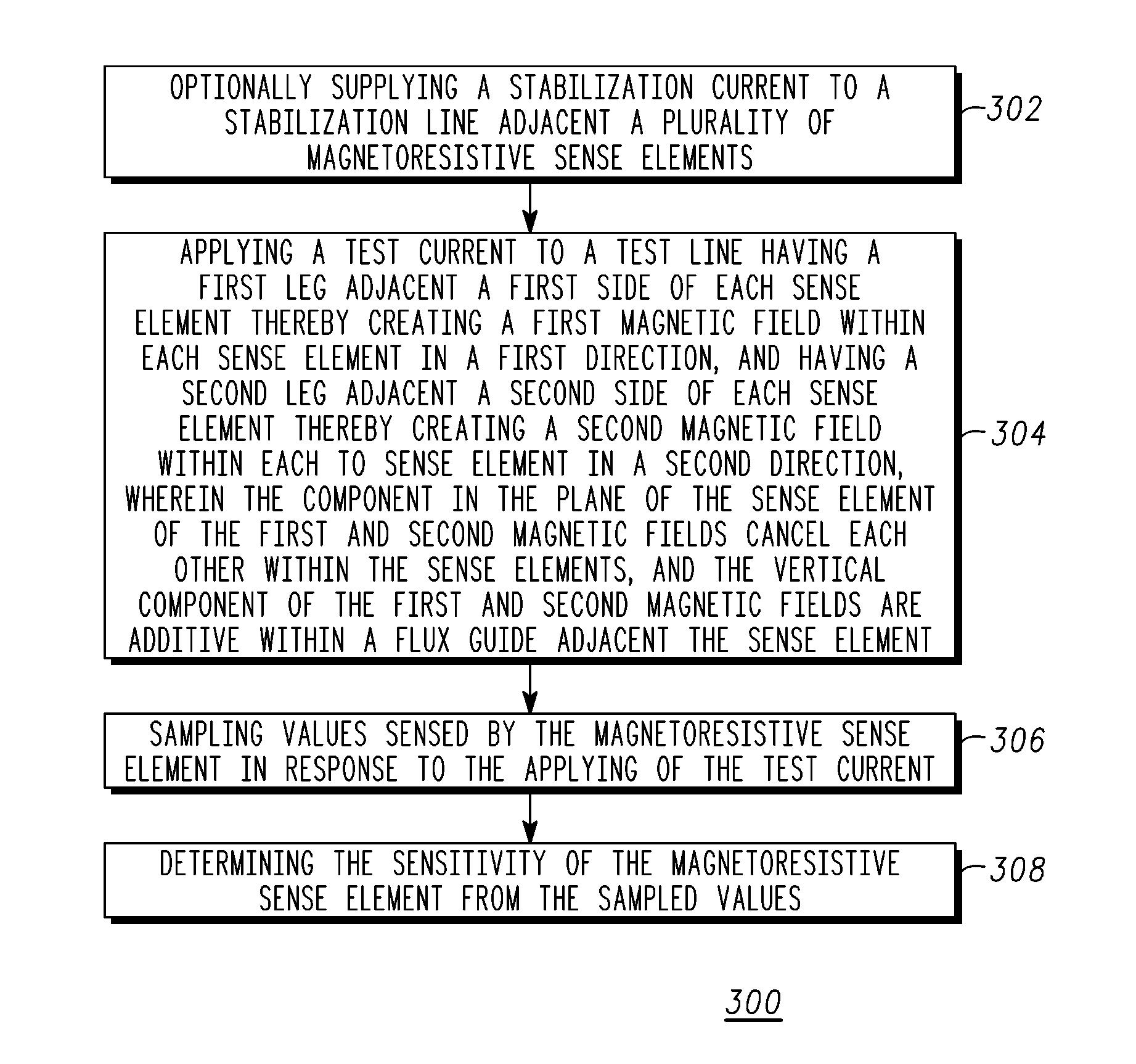
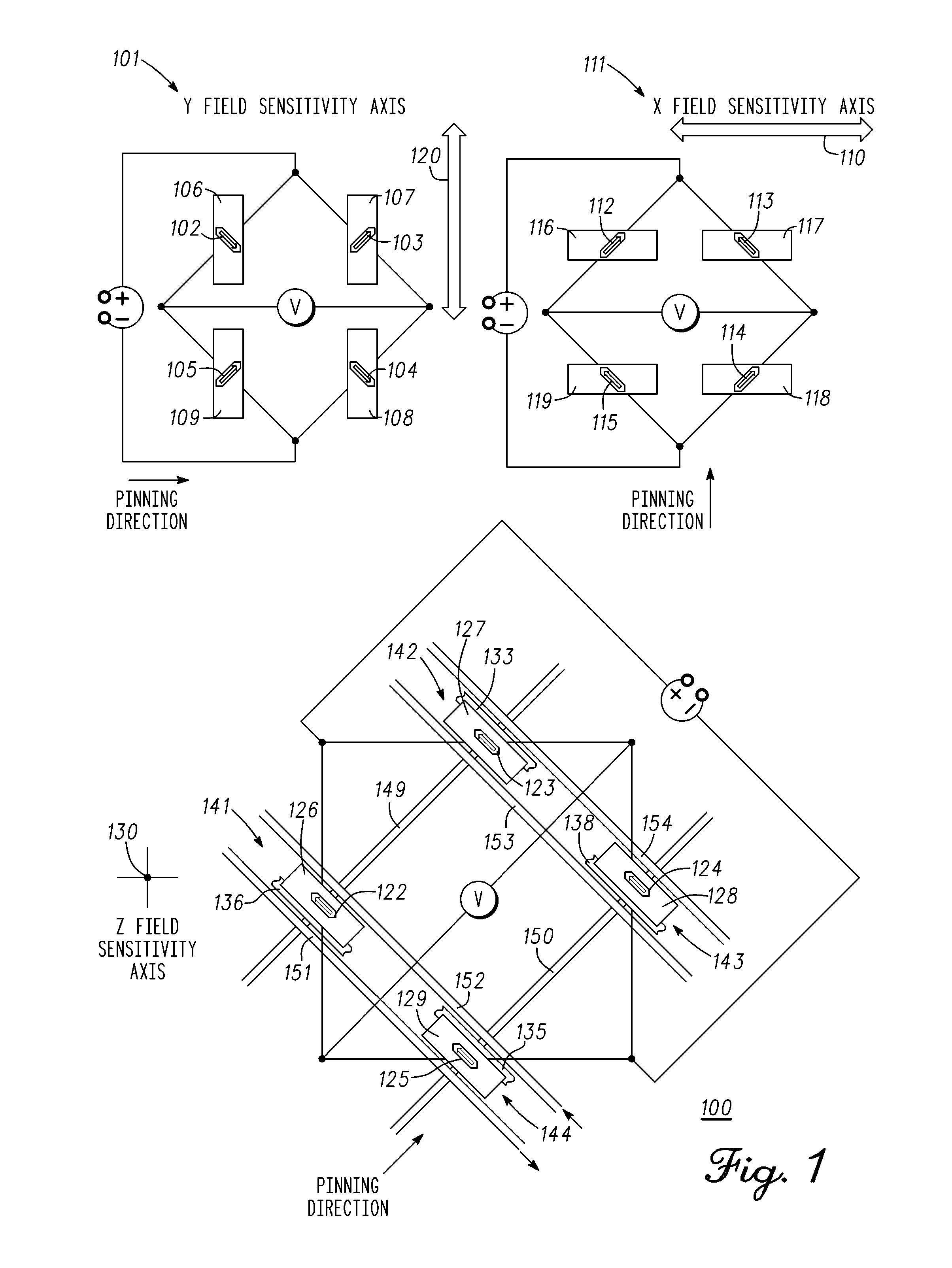
[0016]Through the integration of high aspect ratio vertical bars (flux guides) of a high permeability material, for example, nickel iron (NiFe), whose ends terminate in close proximity to opposed edges and opposite sides of a magnetic sense element, a portion of the Z axis field can be brought into the XY plane. These flux guides serve to capture magnetic flux from an applied field oriented in the Z direction, and in so doing, bend the field lines in a substantially hori...


PUM


Abstract

A structure and method are provided for self-test of a Z axis sensor. Two self-test current lines are symmetrically positioned adjacent, but equidistant from, each sense element. The vertical component of the magnetic field created from a current in the self-test lines is additive in a flux guide positioned adjacent, and orthogonal to, the sense element; however, the components of the magnetic fields in the plane of the sense element created by each of the two self-test current line pairs cancel one another at the sense element center, resulting in only the Z axis magnetic field being sensed during the self-test.

Description

TECHNICAL FIELD[0001]The present invention generally relates to a magnetic field sensing device for sensing magnetic fields in three orthogonal directions and more particularly to a magnetoelectronic three axis field sensor providing on-chip testing and calibration.BACKGROUND[0002]Sensors are widely used in modern systems to measure or detect physical parameters, such as direction, position, motion, force, acceleration, temperature, and pressure. While a variety of different sensor types exist for measuring these and other parameters, they all suffer from various limitations. For example, inexpensive low field sensors, such as those used in an electronic compass and other similar magnetic sensing applications, may comprise anisotropic magnetoresistance (AMR) based devices. In order to arrive at the required sensitivity and reasonable resistances that mesh well with complementary metal-oxide semiconductors (CMOS), the chip area of such sensors are generally in the order of square mil...

Claims


Application Information

Patent Timeline
IPC IPC(8): G01R35/00G01R33/09
CPCG01R35/00G01R33/0035G01R33/0206G01R33/093G01R35/005G01R33/09
Inventor LIU, LIANJUNMATHER, PHILLIP
Owner EVERSPIN TECHNOLOGIES
Why Eureka
Try Eureka