Zero emissions pneumatic-electric engine

a technology of electric motors and pneumatics, applied in the field of engines, can solve the problems of low reluctance, weak magnetic field, and reduced engine efficiency

Inactive Publication Date: 2013-11-14
CHARITY III HERMAN TYRONE
View PDF9 Cites 7 Cited by
  • Summary
  • Abstract
  • Description
  • Claims
  • Application Information

AI Technical Summary

Benefits of technology

[0037]Briefly, a reciprocating engine system embodiment of the present invention includes one or more pairs of piston assemblies fitted with embedded magnets in positions that can be alternately repelled and attracted by electromagnetic coils within each of the piston cylinders. The magnetic piston assemblies are connected by rods to a crankshaft with a flywheel. The electromagnetic coils are ported to allow air compressor intake and exhaust flows th

Problems solved by technology

A seal needs to be made for the pistons as they slide within the cylinder walls so that high pressure gas does not leak past and reduce the efficiency of the engine.
This means that the magnetic field

Method used


Image

  • Zero emissions pneumatic-electric engine
  • Zero emissions pneumatic-electric engine
  • Zero emissions pneumatic-electric engine

Examples


first embodiment

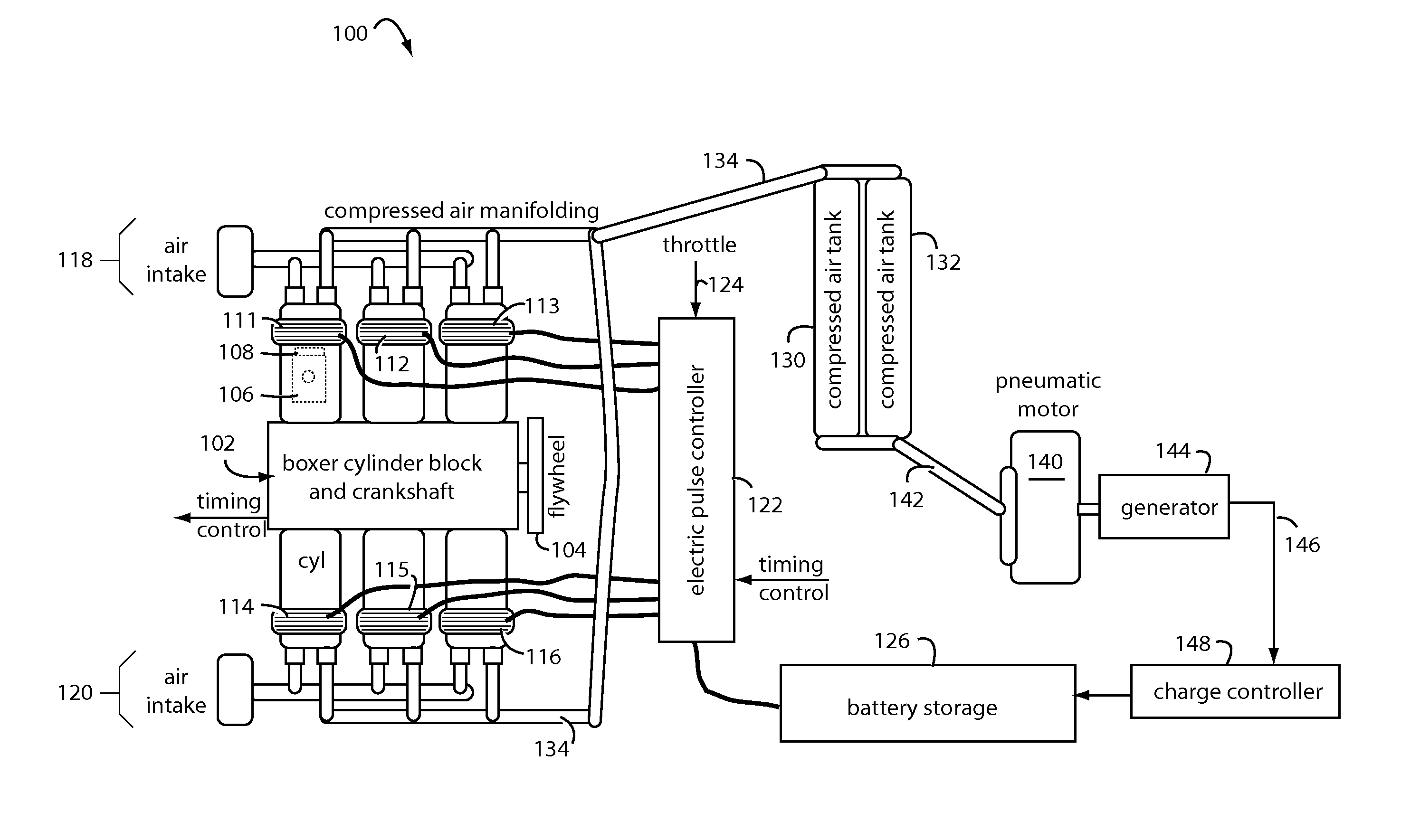
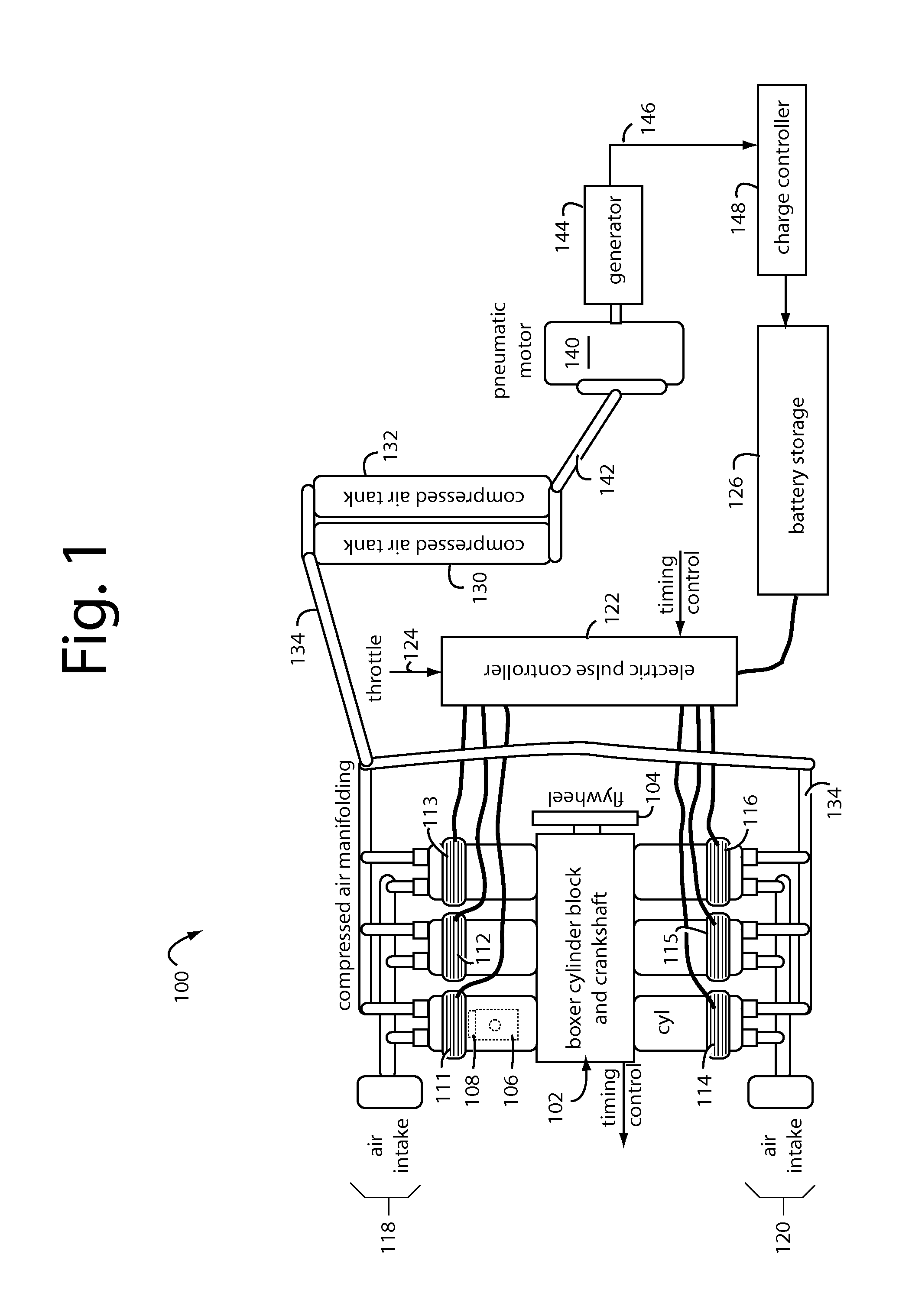
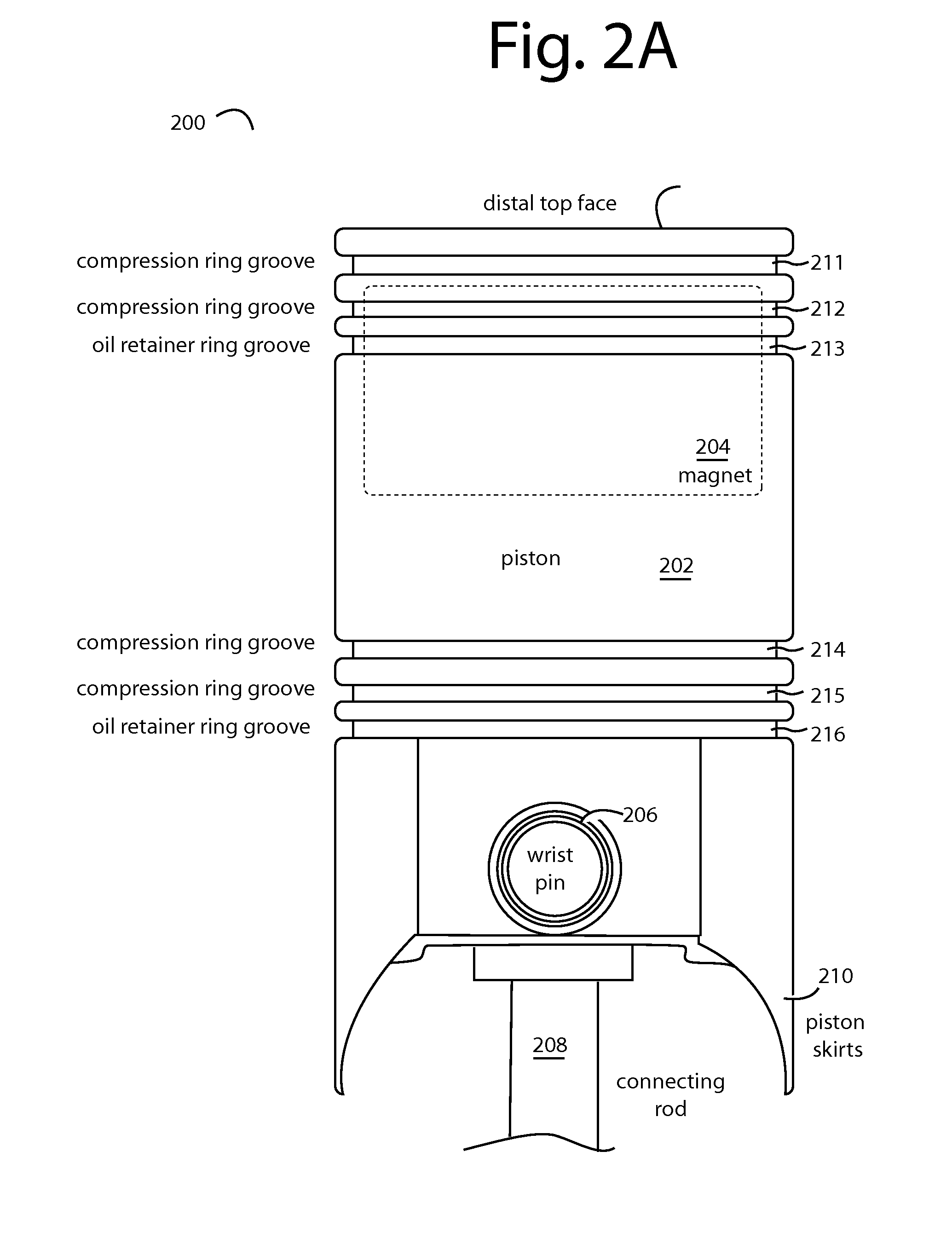
[0058]the present invention provides reciprocating electric engine with an electro-magnetic pulsed coil firing an electro-magnetic element loaded piston, where the piston face and the electro-magnetic coil face have opposing magnetic fields.

second embodiment

[0059]the present invention provides an electro-magnetic means through polarity switching that captures the magnet in a piston and acts upon it in such a manner that pushes and pulls the piston assembly. This configuration captures the piston in an electro-magnetic collapsing, energizing, and reversing manner.

third embodiment

[0060]the present invention provides an electromagnetic means to pull or attract the magnet in a piston serving to increase the reciprocating speeds capability by not reversing polarity of the magnetic field.


PUM


Abstract

A reciprocating engine has several piston assemblies fitted with embedded magnets in positions that can be alternately repelled and attracted by electromagnetic coils within each of the piston cylinders. The magnetic piston assemblies are connected by rods to a crankshaft with a flywheel. The electromagnetic coils are vented to allow air intake and exhaust to flow through to the piston chambers. Valves and valve timing are controlled relative to the crankshaft rotation such that compressed air can be generated and stored in tanks. The compressed air is used to power air motors to turn electric generators for on-board battery charging. The reciprocating electric engine is configured to idle at a speed that overcomes friction.

Description

BACKGROUND OF THE INVENTION[0001]1. Field of the Invention[0002]The present invention generally relates to engines, and more particularly to zero emissions configurations of pneumatic and electric motors suitable for on-board use in vehicles.[0003]2. Background of the Invention[0004]The reciprocating engine, also often known as a piston engine, is a heat engine that uses one or more reciprocating pistons to convert pressure into a rotating motion. The main type is the internal combustion engine, used extensively around the world in motor vehicles.[0005]There may be one or more pistons. Each piston is inside a cylinder into which a gas is introduced, either already hot and under pressure (steam engine), or that gets heated inside the cylinder by either ignition of a fuel air mixture (internal combustion engine) or by contact with hot heat exchangers inside the cylinders (Sterling engine). When hot gases expand, they can do work, e.g., pushing the piston to the bottom of the cylinder....

Claims


Application Information

Patent Timeline
IPC IPC(8): F04B35/04
CPCF04B35/04F04B39/122F04B53/1082F04B53/12F04B53/14
Inventor CHARITY, III, HERMAN TYRONE
Owner CHARITY III HERMAN TYRONE
Why Eureka
Try Eureka