Film Formation Apparatus, Method for Forming Film, Method for Forming Multilayer Film or Light-Emitting Element, and Method for Cleaning Shadow Mask

a film formation apparatus and film technology, applied in the direction of solid-state devices, vacuum evaporation coatings, coatings, etc., can solve the problems of increasing the size and area of the film formation apparatus, requiring large-scale expensive apparatuses to have high operation rates, and reducing the rate of operation per film formation chamber or film formation region. , to achieve the effect of reducing the rate of operation

Inactive Publication Date: 2013-11-14
SEMICON ENERGY LAB CO LTD
View PDF10 Cites 18 Cited by
  • Summary
  • Abstract
  • Description
  • Claims
  • Application Information

AI Technical Summary

Benefits of technology

[0114]According to one embodiment of the present invention, a film formation apparatus in which the number of continuously stacked films can be flexibly changed while a decrease in the rate of operation of a film formation chamber or a film formation region provided in the film formation apparatus is suppressed can be provided. Further, a method for forming a multilayer film in which the number of continuously stacked films can be flexibly changed can be provided. Furthermore, a method for manufacturing a light-emitting element can be provided.

Problems solved by technology

Therefore, an increase in the number of films which can be stacked with the film formation apparatus results in an increase in the size and area of the film formation apparatus.
Large-scale expensive apparatuses are required to have high rates of operation.
Even when the rate of operation of the film formation apparatus is increased using only part of the film formation chambers in such a manner, the rate of operation per film formation chamber or film formation region is low, which is not cost efficient.
Moreover, in the case where the film formation material attached to a shadow mask is removed by being vaporized by irradiation with plasma, low removal speed leads to low work efficiency and low cost efficiency.
Consequently, a complicated operation is needed for management of used shadow masks.

Method used


Image

  • Film Formation Apparatus, Method for Forming Film, Method for Forming Multilayer Film or Light-Emitting Element, and Method for Cleaning Shadow Mask
  • Film Formation Apparatus, Method for Forming Film, Method for Forming Multilayer Film or Light-Emitting Element, and Method for Cleaning Shadow Mask
  • Film Formation Apparatus, Method for Forming Film, Method for Forming Multilayer Film or Light-Emitting Element, and Method for Cleaning Shadow Mask

Examples


embodiment 1

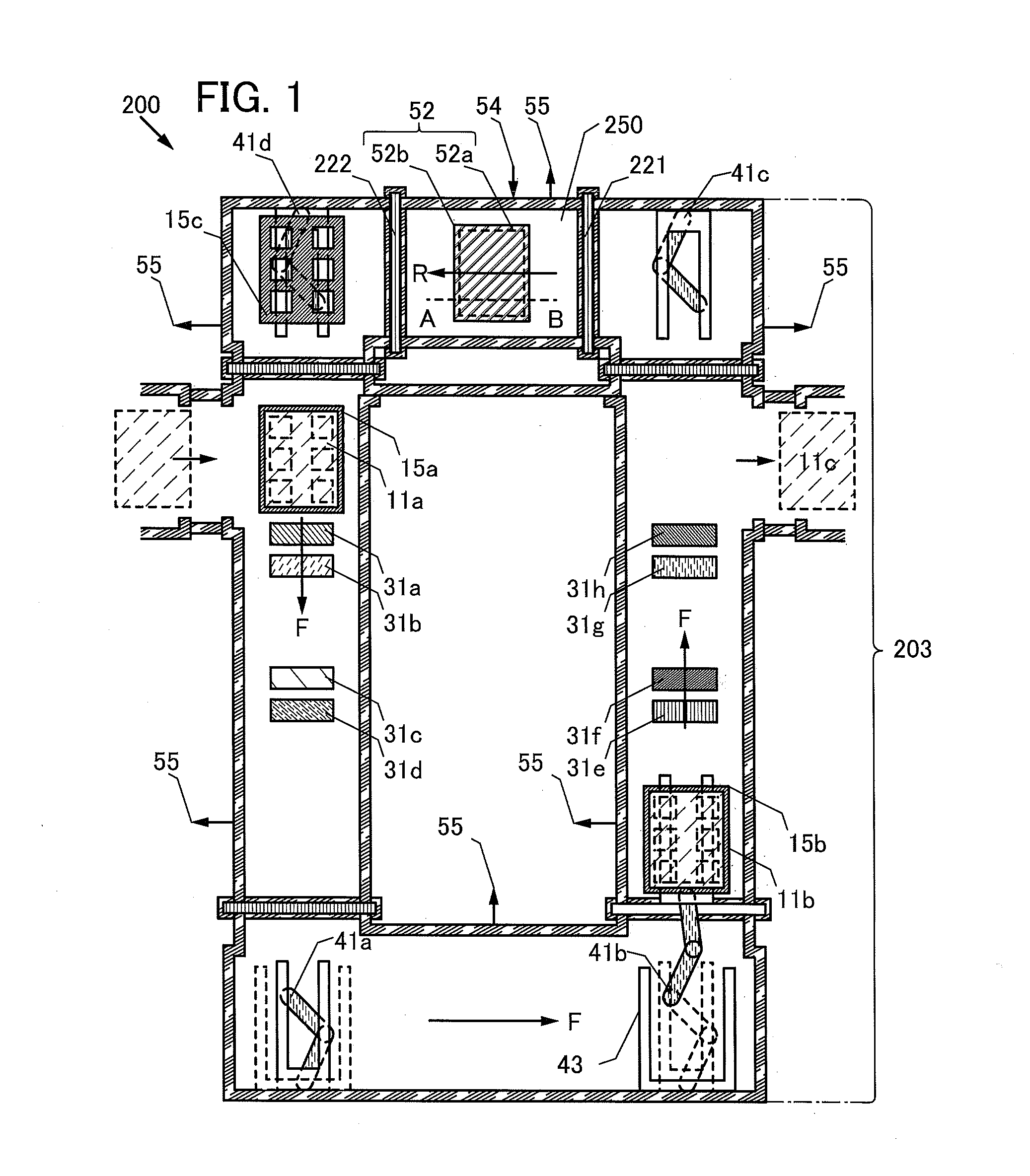
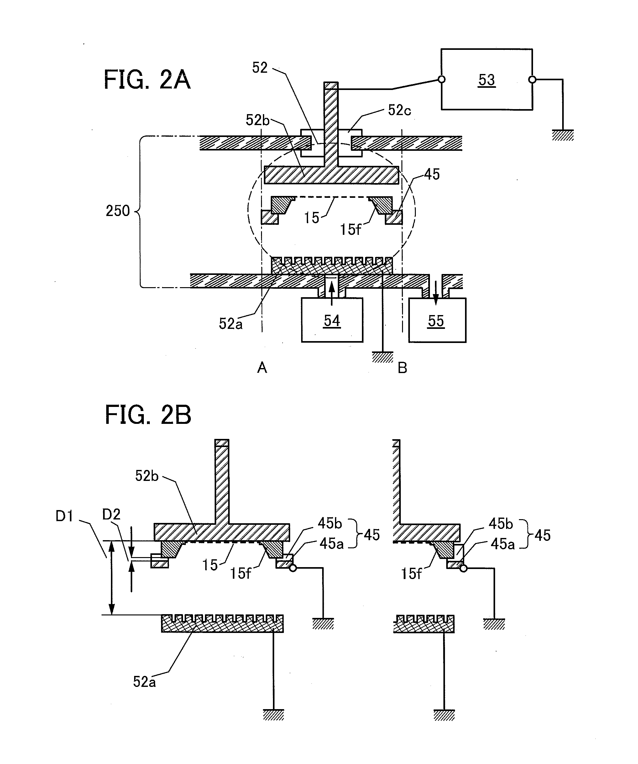
[0135]In this embodiment, a structure of a film formation apparatus of one embodiment of the present invention will be described with reference to FIG. 1 and FIGS. 2A and 2B. FIG. 1 is a top view of a structure of a film formation apparatus of one embodiment of the present invention. FIGS. 2A and 2B are side views of the structure of the film formation apparatus, which each include a cross section taken along line A-B in FIG. 1.

[0136]A film formation apparatus 200 described in this embodiment includes a removal chamber 250 and a film formation chamber 203. A first sluice valve 221 and a second sluice valve 222, which each connect the removal chamber 250 to the film formation chamber 203, are provided apart from each other between the removal chamber 250 and the film formation chamber 203. This enables a shadow mask to be carried in or carried out from / to one of the removal chamber 250 and the film formation chamber 203 to / from the other.

[0137]The film formation apparatus 200 include...

embodiment 2

[0191]In this embodiment, a structure of a film formation apparatus of one embodiment of the present invention will be described with reference to FIGS. 4A and 4B. FIG. 4A is a block diagram schematically showing the structure of the film formation apparatus of one embodiment of the present invention, and FIG. 4B is a chart showing a method for continuously forming films on a plurality of objects and continuously reproducing used shadow masks with use of the film formation apparatus and the shadow masks in FIG. 4A.

[0192]The film formation apparatus described in this embodiment includes a first removal chamber 250_1 and a second removal chamber 250_2 (see FIG. 4A). Each removal chamber includes a shadow mask stage and a plasma source which are not shown.

[0193]This structure enables a plurality of shadow masks to be concurrently irradiated with plasma in the plurality of removal chambers; thus, film formation materials can be concurrently removed from the plurality of shadow masks. Fu...

embodiment 3

[0208]In this embodiment, an example of a structure of a film formation apparatus of one embodiment of the present invention which can be used for manufacture of a display panel will be described. FIGS. 5A and 5B illustrate structures of a film formation apparatus described in this embodiment. Note that a solid line indicates the track of a shadow mask being transferred through a film formation chamber, and a broken line indicates the track of a shadow mask being transferred through a removal chamber.

[0209]A film formation apparatus 200W illustrated in FIG. 5A is a film formation apparatus which can be used for manufacture of a light-emitting element.

[0210]The film formation apparatus 200W includes a first film formation chamber 203W, a first removal chamber 250W, a second film formation chamber 203C, a second removal chamber 250C, and a carrying-in chamber 211 and a carrying-out chamber 212 for an object. The carrying-in chamber 211 is for carrying in the object to the film formati...


PUM

PropertyMeasurementUnit
diameteraaaaaaaaaa
lengthaaaaaaaaaa
lengthaaaaaaaaaa

Abstract

The inventors have reached the idea of a film formation apparatus including a film formation chamber, a removal chamber, two sluice valves provided apart from each other between the film formation chamber and the removal chamber, and a shadow mask transfer mechanism. The film formation chamber includes an evaporation source, and the removal chamber includes a parallel plate plasma source and a shadow mask stage. The film formation apparatus has a film formation mode in which a shadow mask overlapped with an object is transferred by the shadow mask transfer mechanism and a film is formed on the object; and a cleaning mode in which the shadow mask is irradiated with plasma by the plasma source, the shadow mask being held between an upper electrode and a lower electrode by the shadow mask stage.

Description

BACKGROUND OF THE INVENTION[0001]1. Field of the Invention[0002]The present invention relates to a film formation apparatus, a method for forming a film and a method for forming a multilayer film or a light-emitting element which use the film formation apparatus, and a method for cleaning a shadow mask used in the film formation apparatus.[0003]2. Description of the Related Art[0004]An apparatus which ejects a film formation material towards a surface of an object to deposit the film formation material has been known. For example, a film formation apparatus (also referred to as an evaporation apparatus) which includes a film formation chamber provided with an evaporation source filled with a film formation material and which ejects the vaporized film formation material from the evaporation source to form a film on a surface of an object in the film formation chamber has been known.[0005]A film formation apparatus which can efficiently utilize a film formation material is preferred. ...

Claims


Application Information

Patent Timeline
Patent Type & Authority Applications(United States)
IPC IPC(8): H01L51/50H01L21/67
CPCH01L51/50H01L21/67C23C14/042C23C14/12C23C14/562C23C14/568C23C14/5873H01L27/1266C23C14/24H01J37/32568H01J37/32834H10K71/164H10K85/626H10K85/6572H10K71/00H10K50/00H01J2237/332H01J2237/335
Inventor JINBO, YASUHIROEGUCHI, SHINGOYAMAZAKI, SHUNPEI
Owner SEMICON ENERGY LAB CO LTD
Why Eureka
Try Eureka