plug

a plug and socket technology, applied in the field of plugs, can solve the problems of weak joint strength between the upper valve and the lower valve, risk of infection, valve uncoupling, etc., and achieve the effect of reliably preventing the reusability of the frame body

Inactive Publication Date: 2013-11-14
FUJIFILM CORP
View PDF3 Cites 5 Cited by
  • Summary
  • Abstract
  • Description
  • Claims
  • Application Information

AI Technical Summary

Benefits of technology

[0006]In the forceps plug disclosed in JP2007-185371A, the upper valve and the lower valve are integrally made of a rubber member, and therefore, the configuration thereof is simple. However, since both valves are made of a rubber member, joint strength between the upper valve and the lower valve is weak. Therefore, there is possibility that the lower valve may be uncoupled from the channel opening portion together with the treatment tool, or the upper valve may be uncoupled from the lower valve by frictional resistance or hooking when removing the treatment tool. If the engagement between the lower valve and the upper valve is released and uncoupled, there is a risk of infection due to dispersed body fluid or the like.
[0007]Furthermore, the forceps plug disclosed in JP2005-177080A or JP2005-224529A is a disposable type. Therefore, the frame body is provided with a breaking portion, and reuse of the forceps plug is prevented by breaking the breaking portion after use so as to restrict the remount of the channel opening portion. Thus, since the upper valve is engaged with the frame body having rigidity, it is possible to maintain joint strength therebetween compared to the engagement between parts made of a rubber member as described in JP2007-185371A. Therefore, the upper valve is prevented from uncoupling together with the treatment tool when removing the treatment tool.

Problems solved by technology

However, since both valves are made of a rubber member, joint strength between the upper valve and the lower valve is weak.
Therefore, there is possibility that the lower valve may be uncoupled from the channel opening portion together with the treatment tool, or the upper valve may be uncoupled from the lower valve by frictional resistance or hooking when removing the treatment tool.
If the engagement between the lower valve and the upper valve is released and uncoupled, there is a risk of infection due to dispersed body fluid or the like.
Therefore, it is necessary for the frame body to be made of a material having compatibility with the living body, whereby there is a problem in that available material for the frame body is limited.
Subsequently, a plurality of undercut parts are generated at molds when molding the frame body, and therefore, manufacturing cost for the molds is increased.
Also, there is a problem in that molding suitability is deteriorated due to the plurality of undercut parts.
As a result, there is a problem in that man-hours for assembly are increased.

Method used


Image

  • plug
  • plug
  • plug

Examples


first embodiment

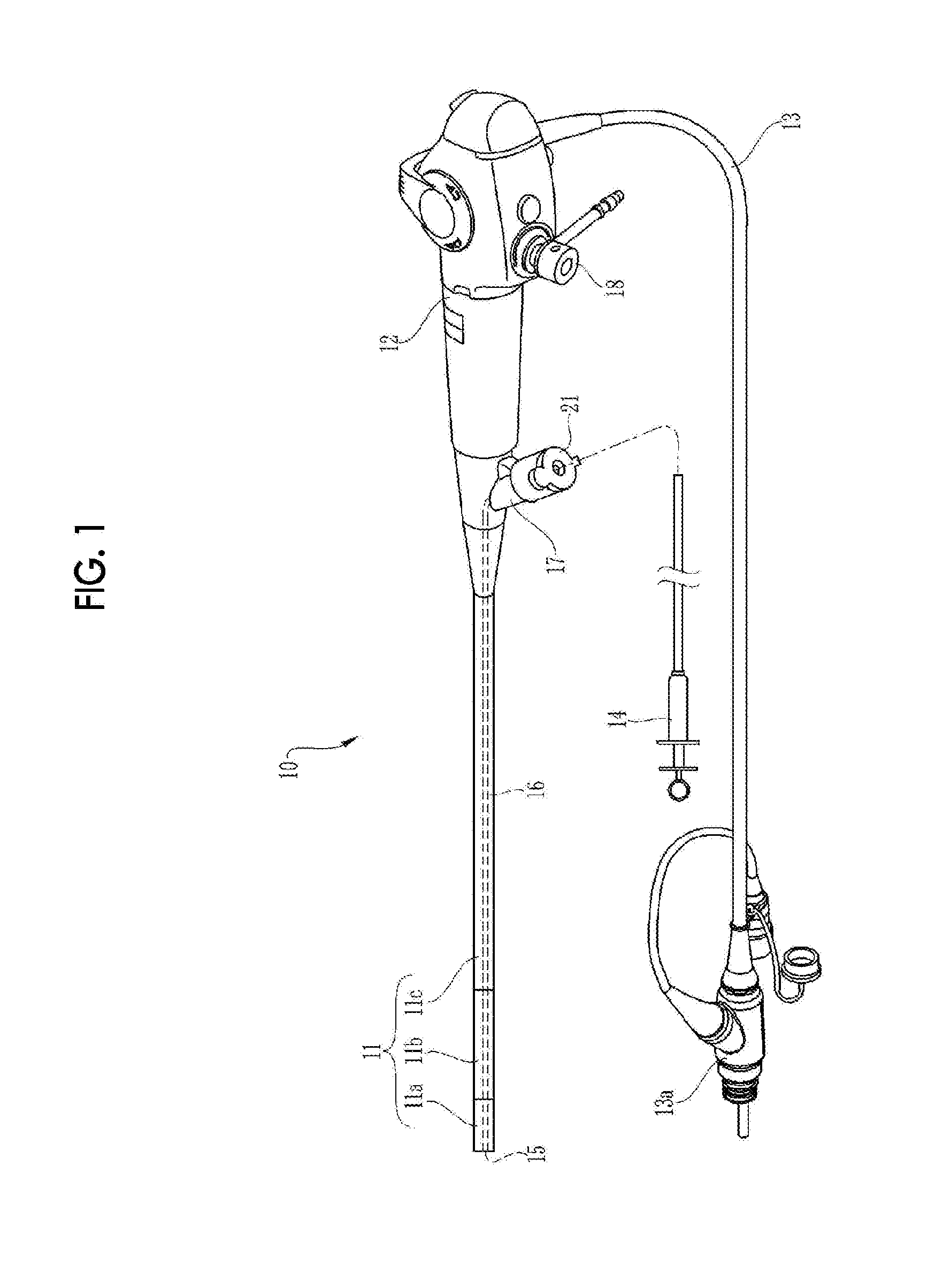
[0036]As shown in FIG. 1, an endoscope 10 is a bronchoscope inserted into a trachea, for example, and includes an insertion portion 11 inserted into a trachea, an operation portion 12 continuously provided at a base end portion of the insertion portion 11 and an universal code 13 joined to the operation portion 12. The universal code 13 is joined to a processor unit, a light source device (not shown) or the like via a complex type connector 13a.

[0037]The insertion portion 11 is divided into a hard distal end portion 11a, a bending portion 11b freely bendable and a flexible tube portion 11c having flexibility in order from a tip end side to the base end side. An observation window or an illumination window (not shown) aside from a treatment tool outlet 15 which is used as an outlet of a treatment tool 14 such as a forceps are provided on a tip end surface of the hard distal end portion 11a. An image sensor (not shown) or the like is disposed inside the observation window, and an opt...

second embodiment

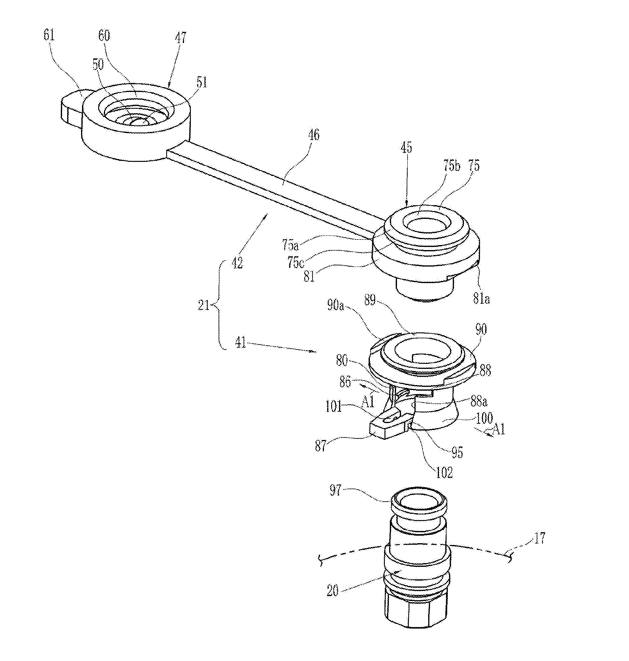
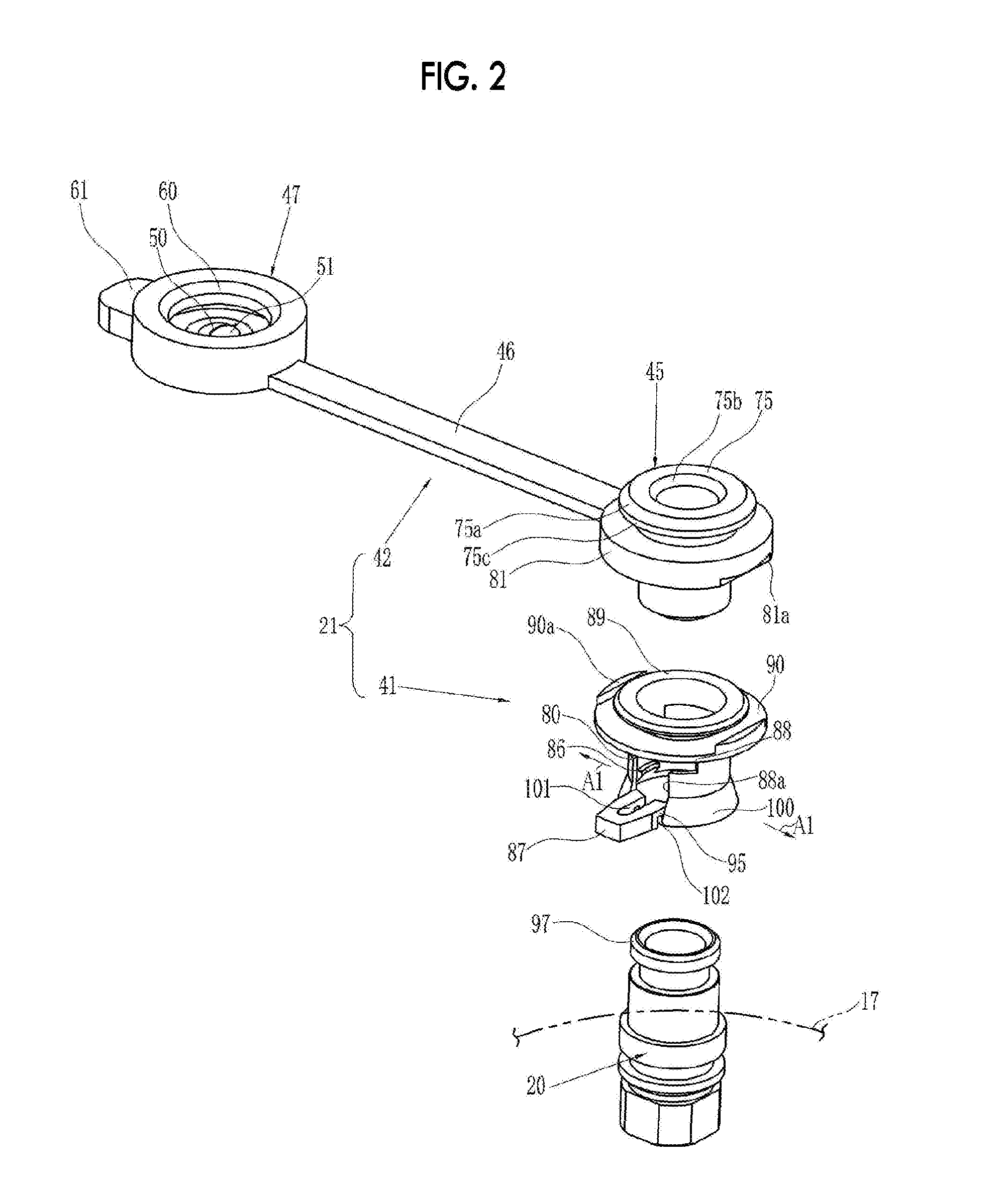
[0058]Next, another embodiment where figures of the knob portion of the attachable and detachable valve and the receiving portion of the frame body are changed will be described. As shown in FIG. 7, a knob portion 112 extending in a diametrical direction of the attachable and detachable valve 111 on an opposite side to the connection side of the connecting band 114 is integrally formed with an attachable and detachable valve 111 of the plug 109 of a second embodiment. On the outer circumferential surface of the receiving portion 90 of the frame body 110, an engaging claw 113 which is inserted into an engaging hole 112a of the knob portion 112 and engaged with the knob portion 112 is integrally formed with the receiving portion 90. The engaging claw 113 is formed in a direction different from a direction where the treatment tool 14 (see FIG. 1) is pulled out. In addition, the length of the connecting band 114 is shorter than that of the connecting band 46 in the first embodiment and ...


PUM


Abstract

The fixed valve and the attachable and detachable valve are connected to each other via a connecting band, and both are integrally made of elastomer. A frame body is constituted of a rigid body made of plastic. A flange and a receiving portion are formed on an upper portion of the frame body. A second flange is formed on a lower end of the fixed valve. The fixed valve is installed on the frame body by engaging the second flange with flange. The second flange is prevented from being separated from the flange of the second flange by interposing a part of the second flange between the flange and the receiving portion. The fixed valve is securely installed on the frame body, whereby the fixed valve is prevented from uncoupling when removing a treatment tool.

Description

BACKGROUND OF THE INVENTION[0001]1. Field of the Invention[0002]The present invention relates to a plug mounted on a channel opening portion of a treatment tool channel of an endoscope.[0003]2. Description of the Related Art[0004]In the field of medicine, various treatments aside from the intracorporeal observation have been executed with respect to a diseased part by inserting an insertion portion of an endoscope into the body of a patient. Specifically, various treatments such as excising or sampling of a diseased part are carried out by inserting various treatment tools such as a forceps or an incision tool from a channel opening portion provided in an operation portion of the endoscope into a treatment tool channel inside an insertion portion and protruding it from an insertion portion tip end.[0005]A forceps plug (plug) enabling the treatment tool to be inserted when performing treatments is mounted on the channel opening portion (see JP2007-185371A, JP2005-177080A and JP2005-2...

Claims


Application Information

Patent Timeline
Patent Type & Authority Applications(United States)
IPC IPC(8): A61B1/00
CPCA61B1/00137
Inventor YAMANE, KENJI
Owner FUJIFILM CORP
Why Eureka
Try Eureka