Method of manufacturing an electrode for an energy storage device

a manufacturing method and energy storage technology, applied in the manufacture of cables/conductors, conductive materials, metallic material coating processes, etc., can solve the problems of limited degradation by charge and discharge, and achieve the effect of enhancing the joint strength between the positive electrode and the negative electrode, reducing the resistance value, and reducing the contact area

Active Publication Date: 2016-06-14
SENJU METAL IND CO LTD
View PDF31 Cites 0 Cited by
  • Summary
  • Abstract
  • Description
  • Claims
  • Application Information

AI Technical Summary

Benefits of technology

[0024]In the electrode for energy storage device, the manufacturing method thereof and the connecting method thereof according to this invention, the positive electrode containing Al and the negative electrode containing metal, which is different species from Al, can be soldered so that jointing strength between the positive electrode and the negative electrode can be enhanced. Further, the contacting area is increased in comparison with the conventional jointing by the spot-welding or the conventional fastening by a bolt so that the resistance value at the contacting point is reduced, thereby enabling the voltage drop of the energy storage device by contact resistance to be reduced. As a result thereof, it is possible to supply the voltage of the energy storage device effectively to a load without any drop of the voltage thereof.

Problems solved by technology

Accordingly, it has merits such that its voltage is higher than that of the electric double layer capacitor, its internal resistance is less than that of the secondary battery, charge and discharge are carried out for a short time of period, and any degradation by the charge and discharge is limited so that it has a long life for goods.

Method used


Image

  • Method of manufacturing an electrode for an energy storage device
  • Method of manufacturing an electrode for an energy storage device
  • Method of manufacturing an electrode for an energy storage device

Examples


embodiment 1

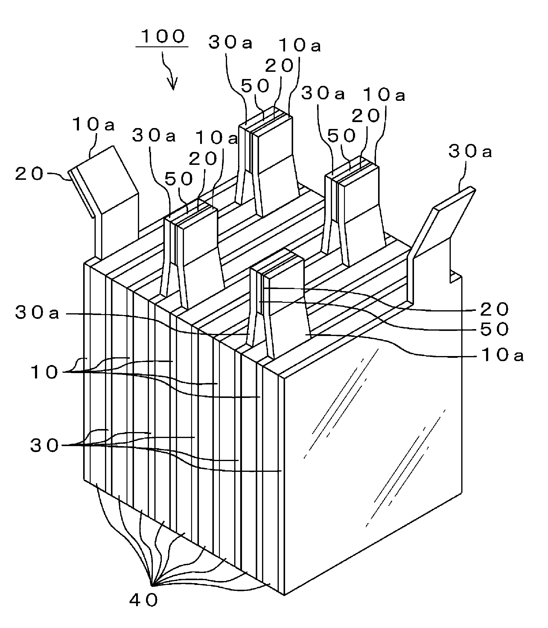
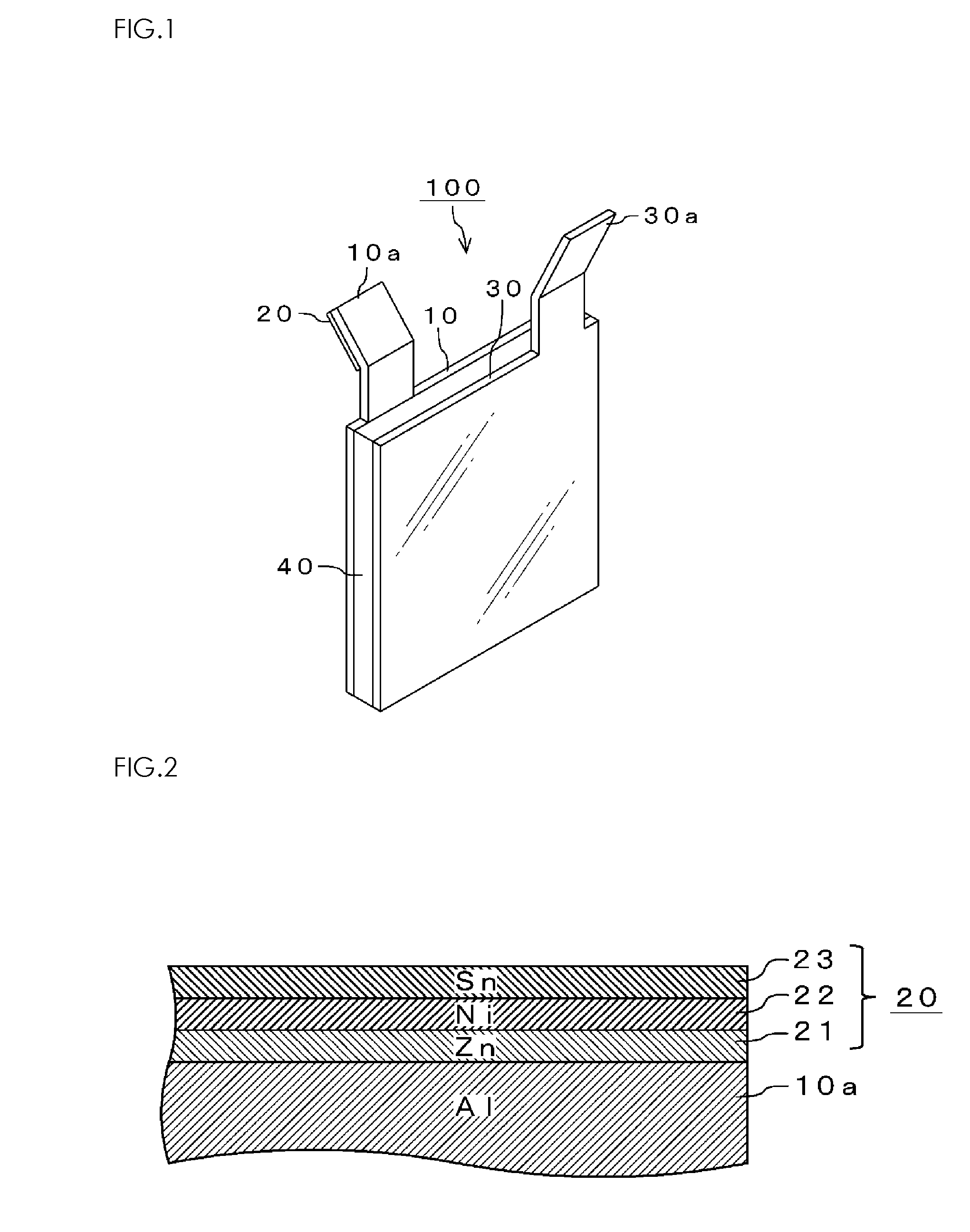
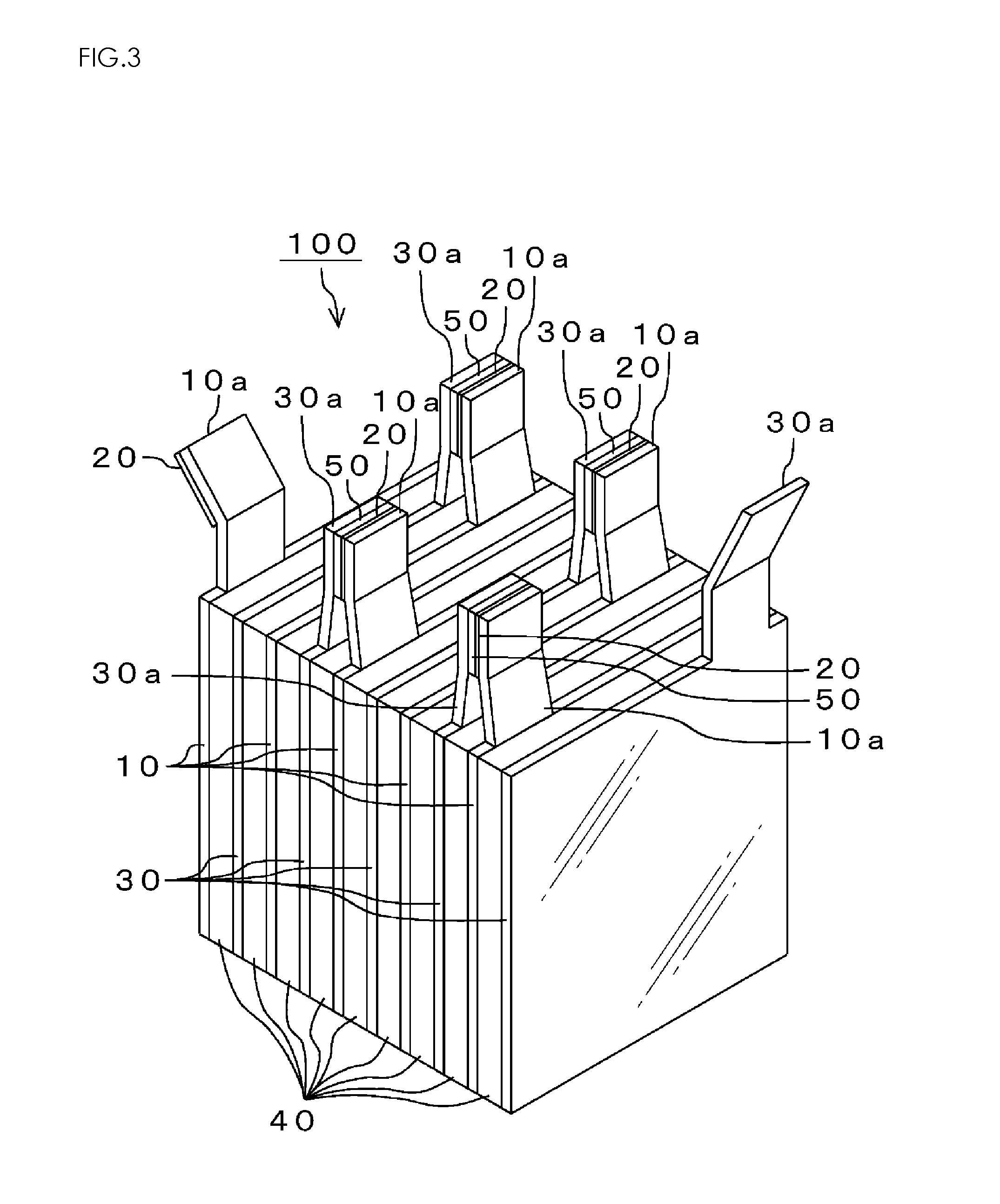
[0044]Next, the following will describe a manufacturing method of the plating layers 20 formed on the Al positive electrode 10 of the energy storage device 100 according to this invention. The plating layers 20 are manufactured according to the following procedures 1 through 5.

[0045]

[0046]The connecting terminal part 10a having a dimension of a length of 70 mm, a width of 50 mm, and a thickness of 0.2 mm is dipped and degreased by using organic solvent.

[0047]

[0048]The degreased connecting terminal part 10a is washed by water and alkali-etched and then, is dipped into acid solution (etchant) so that its surface is made rough. By this step, the connecting terminal part 10a composed of Al and the Zn layer 21 are favorably adhered closely to each other.

[0049]

[0050]The etched connecting terminal part 10a is dipped into zincate bath in which ZnO, Zn, NaOH and the like are dissolved with water to form Zn plating (Zn layer 21).

[0051]In order to wash liquid zincate adhered to Zn-plated conne...

embodiment 2

[0059]The Al positive electrode 10 having the plating layers 20 formed by the first embodiment and the Cu negative electrode 30 are soldered to each other using resin flux cored solder. As the resin flux cored solder, RMA08 (manufactured by SENJU METAL INDUSTRY Co., LTD) is used, and it is soldered under a condition such that temperature of a tip of soldering iron is 300 degrees C. and a period of time for soldering is 10 seconds.

[0060]As a comparison example 1, it is made such that Al positive electrode and Cu negative electrode are directly soldered by wire solder composed of Sn-15Zn (mass %). Incidentally, in this soldering, the soldering is carried out with flux being used.

[0061]As a comparison example 2, it is made such that Al positive electrode and Cu negative electrode are connected to each other by the spot-welding using ultrasonic wave.

[0062]In Table 1, a measured result of jointing strength of the Al positive electrode and the Cu negative electrode in each of the embodime...

embodiment 3

[0070]Jointed samples were made by the Al positive electrode and the Cu negative electrode of the embodiment 1 and the comparison examples 1 and 2 and resistance value and voltage value of the jointed sample thus made were measured by a microohm meter using Kelvin clips according to four-terminal method. This measurement condition was such that the samples of the embodiment 1 and the comparison examples 1 and 2 were put into a thermostat oven having ambience temperature of 85 degrees C. and humidity of 85% and an electric current of 100 A in which ON / OFF were repeated every second flowed through the samples.

[0071]FIG. 5 is a diagram showing characteristics example relating to resistance value of the jointed samples in which a vertical axis indicates resistance value (μΩ) of the jointed samples and a horizontal axis indicates repeated frequency (×1000) on ON / OFF of electric current of 100 A. As shown in FIG. 5, the resistance values of the jointed sample in the embodiment 1 are shown...


PUM

PropertyMeasurementUnit
thicknessaaaaaaaaaa
thicknessaaaaaaaaaa
thicknessaaaaaaaaaa

Abstract

Zn layer 21 or Zn alloy layer, Ni layer 22, and Sn layer 23 or Sn alloy layer are formed on a connecting terminal part 10a of a positive electrode composed of Al by plating. Accordingly, this can solder Cu negative electrode, which is composed of metal that is different species from Al, through Sn layer 23 or Sn alloy layer so that jointing strength of the Al positive electrode and the Cu negative electrode can be enhanced. Further, since the contacting area is increased in comparison with the conventional jointing by the spot-welding or the conventional fastening by a bolt so that the resistance value at the contacting point is reduced, the voltage drop of the energy storage device by contact resistance can be reduced.

Description

CROSS-REFERENCE TO RELATED APPLICATION[0001]This is a national stage application filed under 35 USC 371 based on International Application No. PCT / JP2011 / 063575 filed Jun. 14, 2011, and claims priority under 35 USC 119 of Japanese Patent Application No. 2010145566 filed Jun. 25, 2010.TECHNICAL FIELD[0002]The present invention relates to an electrode for energy storage device such as electric double layer capacitor, lithium ion capacitor and secondary battery, which is capable of storing any electric energy, a manufacturing method thereof and a connecting method thereof.BACKGROUND TECHNOLOGY[0003]The lithium ion capacitor is expected as being substituted for the electric double layer capacitor or the secondary battery. This lithium ion capacitor is an energy storage capacitor, energy storage efficiency of which is remarkably enhanced by utilizing physical phenomenon of pre-doping of ion to negative electrode. At the present time, the electric double layer capacitor has been used for ...

Claims


Application Information

Patent Timeline
Patent Type & Authority Patents(United States)
IPC IPC(8): H01R43/16C25D5/12H01B13/32H01M2/20C23C18/16C23C18/18C23C18/54H01G11/24H01G11/66C25D5/44H01M2/30H01B1/02C23C18/36C23C18/52H01G11/00C23C18/31C25D7/00H01G4/232H01G11/06H01G11/74H01G11/76H01G11/84H01M50/531H01M50/534
CPCC23C18/1651C23C18/1653C23C18/1827C23C18/54H01G11/24H01G11/66H01M2/202H01M2/30H01B1/023H01B13/32C25D5/12C25D5/44Y02E60/13C23C18/36C23C18/52Y10T29/49147Y02E60/10H01M50/534H01M50/531C23C18/32C23C18/48C25D3/12C25D3/22C25D3/30C25D3/565C25D3/60H01M50/502H01M50/543C23C18/31H01G11/06H01G11/30H01G11/50H01M2004/028
Inventor NAKAMURA, KATSUJITSURUTA, KAICHIOZAKI, YUJIWATARAI, SHIGEAKITAKAGI, HIDENORIOHORI, YUTAKA
Owner SENJU METAL IND CO LTD
Why Eureka
Try Eureka