Method for preparation of core rod assembly for overcladding, and perform and fiber produced from such core rod assembly

a core rod and overcladding technology, which is applied in the direction of cladded optical fibres, glass making apparatus, instruments, etc., can solve the problems of optical fiber breakage, disadvantages and limitations, and the following drawbacks of known heat treatment process steps, so as to reduce physical defects

Inactive Publication Date: 2007-03-22
STERLITE TECHNOLOGIES
View PDF9 Cites 0 Cited by
  • Summary
  • Abstract
  • Description
  • Claims
  • Application Information

AI Technical Summary

Benefits of technology

[0044] The another main object of the present invention is to provide a method for preparation of core rod assembly wherein no stress is formed at and around the joints formed between the glass rod and core rod meaning thereby the core rod assembly produced will not break, due to stress, during its handling and deposition of soot thereon to form the soot preform.
[0052] Yet further particular object of the present invention is to provide a method for preparation of core rod assembly for overcladding wherein possibility of thermal induced stress in the core rod at and around the joint of the core rod and glass rod area is greatly reduced meaning thereby the joint strength is not adversely effected, and hence, the further processing of the produced core rod assembly will be safer and convenient.

Problems solved by technology

The known heat treatment process steps suffer from following drawbacks, disadvantages and limitations.
The main drawback of the known methods of core rod assembly preparation involving conventional process step of heat treatment of opposite ends of the core rod to attach or fix or weld [herein after for convenience referred as to fix or fixing] glass rods thereto is that it causes stress formation at and around the joints formed between the glass rod and core rod.
The stress formation in the core rod assembly has been observed to cause breakage of the core rod assembly during its handling and deposition of soot thereon to form the soot preform.
The another main drawback of the known methods of core rod assembly preparation involving conventional process step of heat treatment of opposite ends of the core rod to fix glass rods thereto is that it causes physical defects, for example cracks and breaks at and around the joints formed between the glass rod and core rod, and physical defects such as cracks and flaws on the surface of the core rod assembly have been observed to cause bubbles and voids in the soot preform produced from such core rod assembly which in-turn results in breakage of the optical fiber during fiber drawing step, and hence, a loss of the productivity of the process.
The another problem of stress formation and formation of physical defects in the core rod assembly during conventional heat treatment process is that the breakage of the core rod assembly may take place at any time during the soot deposition which not only results in total loss of soot deposition, but also causes damage to the burner, because there is every possibility that the core rod assembly will fall on the burner meaning thereby the conventional heat treatment process suffer from time loss, production loss and financial loss.
It has been further observed that the stress formation and formation of physical defects in the core rod assembly also lead to transmission loss in the resulting optical fiber or distortion of other optical parameters, for example, polarization mode dispersion, cutoff wavelength etc.
If conventional heat treatment is performed by graphite resistance method it has been observed that due to relatively higher process time it causes graphite oxidation which in-turn results in formation of oxidation products, for example ash, graphite particles etc. which adheres to the core rod surface, and such contamination of the core rod with unwanted particles results in production of a daughter preform which will produce a fiber having increased transmission loss and poor strength.
Similarly, if conventional heat treatment is performed by lasers, such as carbon dioxide lasers, which are clean heat source to use, power consumption has been observed to be very high rendering the overall process very expensive.
Further, it has also been observed that large amount of thermal induced stress in the core rod at and around the joint of the core rod and glass rod area adversely effects joint strength which upon further processing may shatter the core rod.
Accordingly, the known methods of core rod assembly preparation are observed to be uneconomical for commercial applications.

Method used


Image

  • Method for preparation of core rod assembly for overcladding, and perform and fiber produced from such core rod assembly
  • Method for preparation of core rod assembly for overcladding, and perform and fiber produced from such core rod assembly
  • Method for preparation of core rod assembly for overcladding, and perform and fiber produced from such core rod assembly

Examples


Embodiment Construction

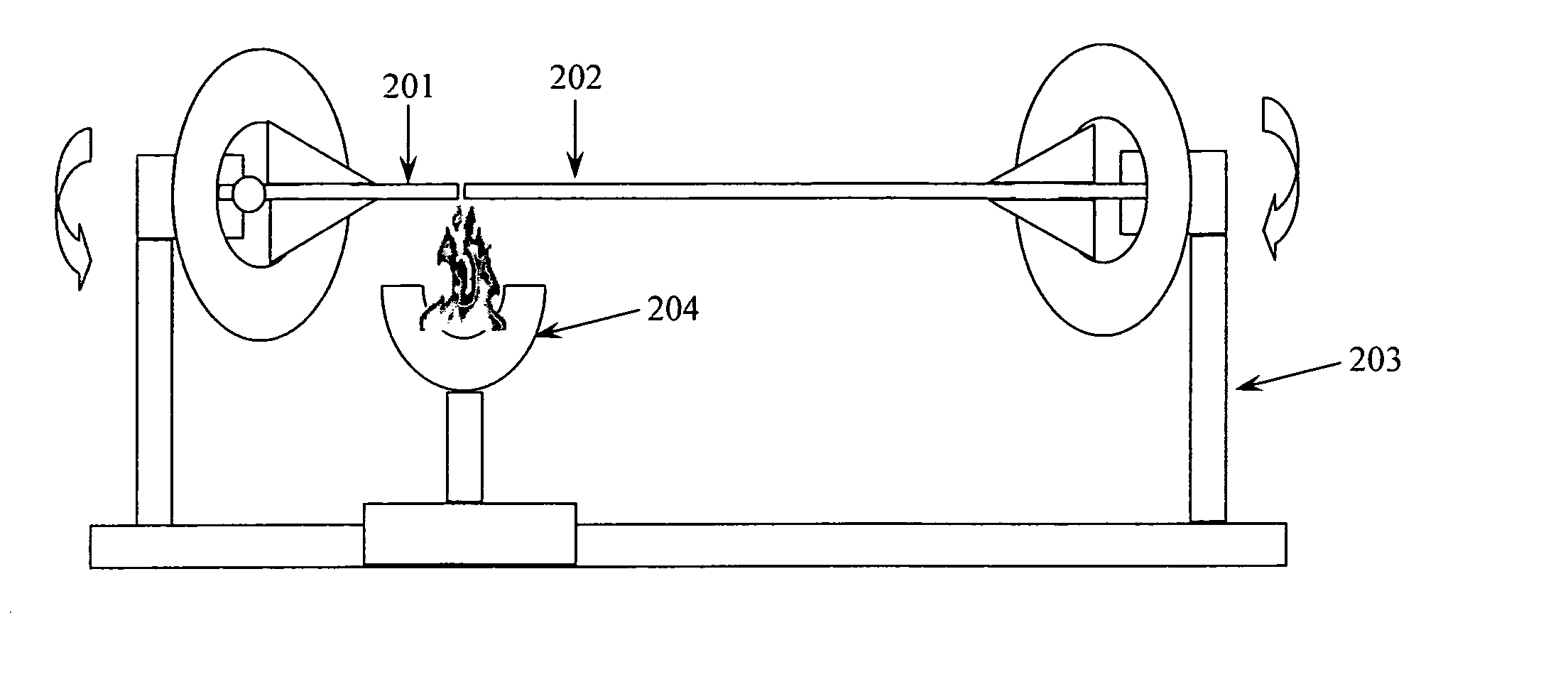
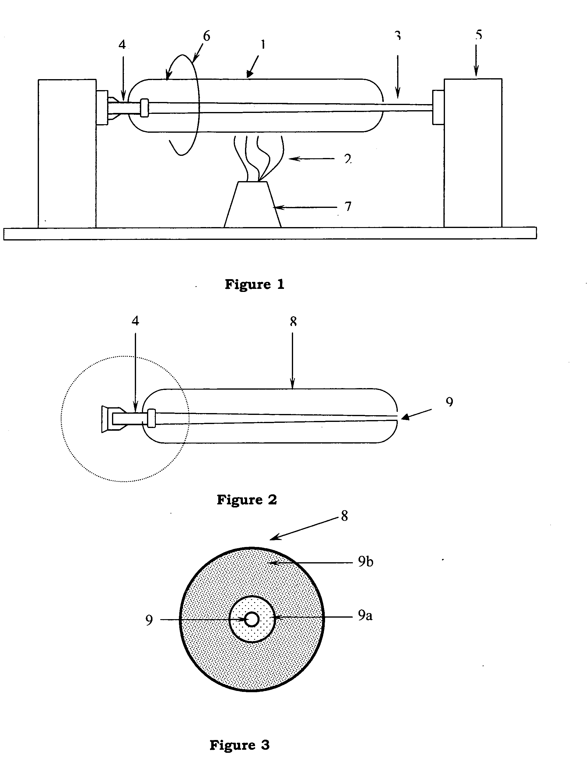
[0076] Accordingly, the present invention relates to a method for preparation of core rod assembly suitable for overcladding comprising the steps of: [0077] a) preparing core rod having reduced diameter; [0078] b) fixing glass rods at each of the opposite ends of the core rod having reduced diameter; characterized in that [0079] c) the core rod with fixed glass rods at its opposite ends obtained in above process step-b) is fire polished in a controlled manner and two step process to produce core rod assembly suitable for overcladding, wherein first step is hard fire polish and second step is soft fire polish.

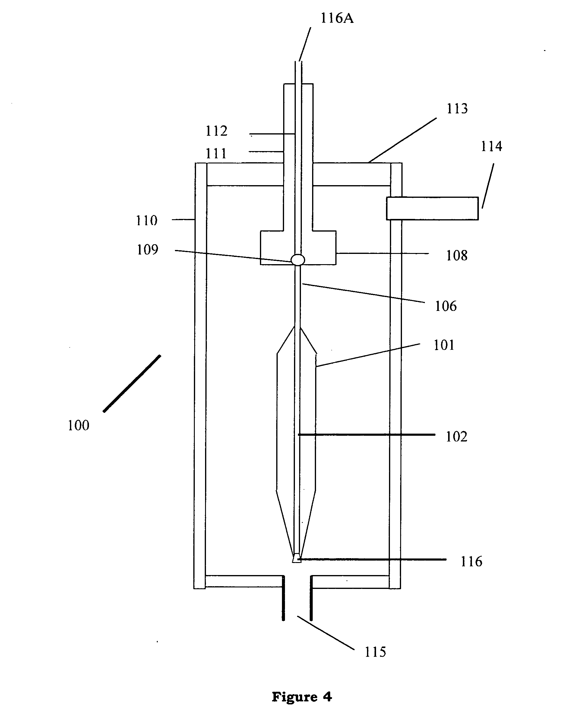
[0080] In accordance with one of the preferred embodiments of the present invention, the overcladding step is performed on the core rod assembly produced in above process step-c) to produce a core rod having overclad referred as soot preform comprising soot porous body having core rod.

[0081] In accordance with another preferred embodiment of the present invention, the soot pre...


PUM

PropertyMeasurementUnit
temperatureaaaaaaaaaa

Abstract

A method for preparation of core rod assembly suitable for overcladding comprising the steps of preparing core rod having reduced diameter, fixing glass rods at each of the opposite ends of the core rod having reduced diameter characterized in that the core rod with fixed glass rods at its opposite ends obtained is fire polished in a controlled manner and two step process to produce core rod assembly suitable for overcladding, wherein first step is hard fire polish and second step is soft fire polish is provided. A core rod assembly, and soot preform prepared from core rod assembly, and a daughter preform prepared from soot preform, and an optical fiber prepared from daughter preform are also provided.

Description

FIELD OF THE INVENTION [0001] The present invention relates to method for preparation of core rod assembly for overcladding. Particularly, the present invention relates to a method for preparation of core rod assembly which is suitable for overcladding so as to form daughter preform which is suitable for fiber draw process. The present invention also relates to a core rod assembly for overcladding, and to the daughter preform and optical fiber produced from such core rod assembly. BACKGROUND OF THE INVENTION [0002] Optical fibers are inherently versatile as a transmission medium for all forms of information, be it voice, video or data. The optical fibers are drawn from an optical fiber preform. The optical fiber of predetermined dimension is drawn either from the solid glass preform [mother preform] or from sintered preform [daughter preform] by subjecting one end of the preform [mother preform or daughter preform] to a high temperature, for example above 2000° C. The sintered prefo...

Claims


Application Information

Patent Timeline
Patent Type & Authority Applications(United States)
IPC IPC(8): G02B6/02C03B18/00C03B37/15
CPCC03B37/01493Y02P40/57
Inventor KULKARNI, PARAGPASARE, DATTATRAY
Owner STERLITE TECHNOLOGIES
Why Eureka
Try Eureka