Integrated Cascading Plant

Inactive Publication Date: 2013-11-21
CITY HLDG AUS
View PDF5 Cites 2 Cited by
  • Summary
  • Abstract
  • Description
  • Claims
  • Application Information

AI Technical Summary

Benefits of technology

[0033]A further aspect of use of a compact water cooled heat exchanger and heat recovery is that the size of the heat rejection

Problems solved by technology

The current Australian refrigeration and air conditioning trade practices are unable to reduce the leakages below 10% of initial charge per year.
While this may not appear much, the amount of supermarkets Australia wide is 1500 and therefore the collective damage caused by their leveraging emissions is high.
However, CO2 has not made much of market penetration due to (i) requirements of high pressures in operating systems and (ii) problems associated with its storage in liquid form.
This gives rise to a significant safety hazard (suffocation) if there is any significant leakage of CO2 into the circulating air.
In order to limit the operating pressures, the cascading medium temperature in conventional refrigeration systems is about −10° C. The upper stage cascading with a synthetic refrigerant mandates cooling to be obtained at a maximum of −15° C. At this temperatu

Method used


Image

  • Integrated Cascading Plant
  • Integrated Cascading Plant
  • Integrated Cascading Plant

Examples


Embodiment Construction

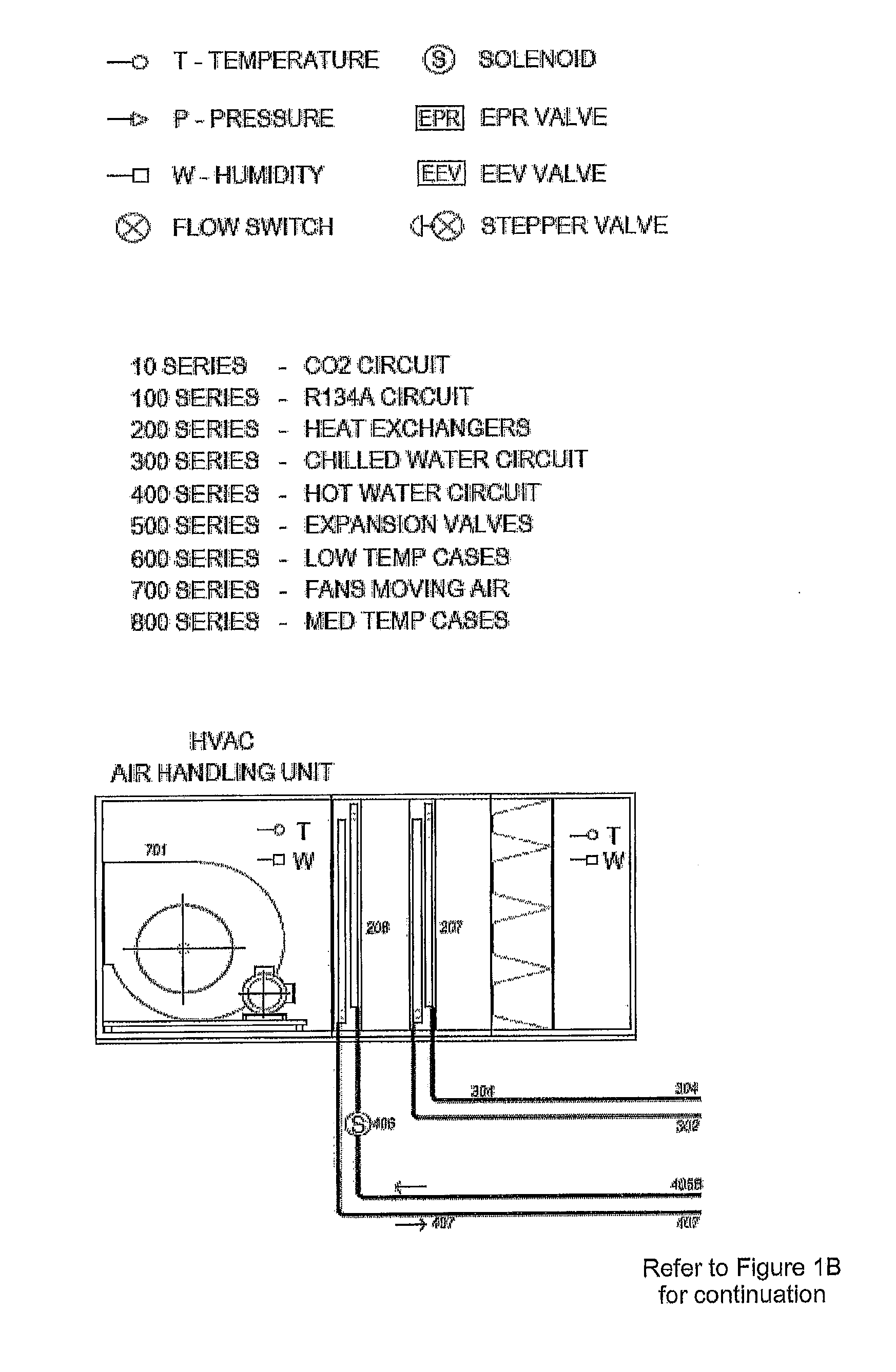
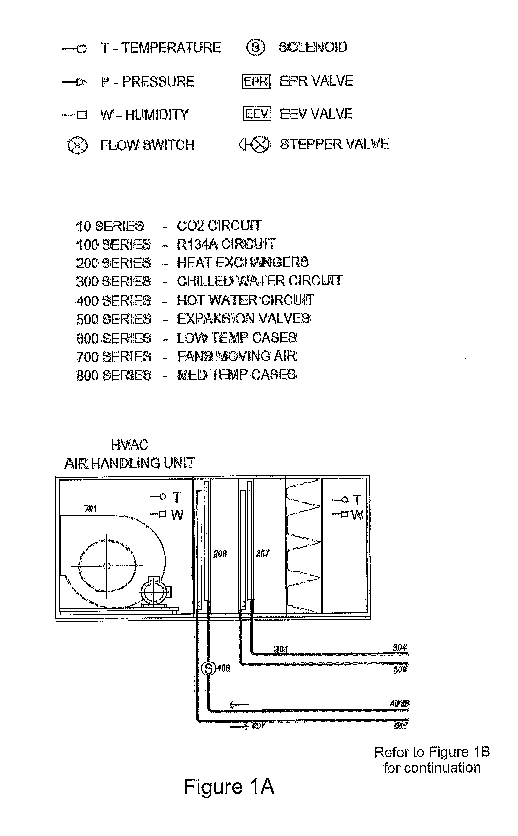
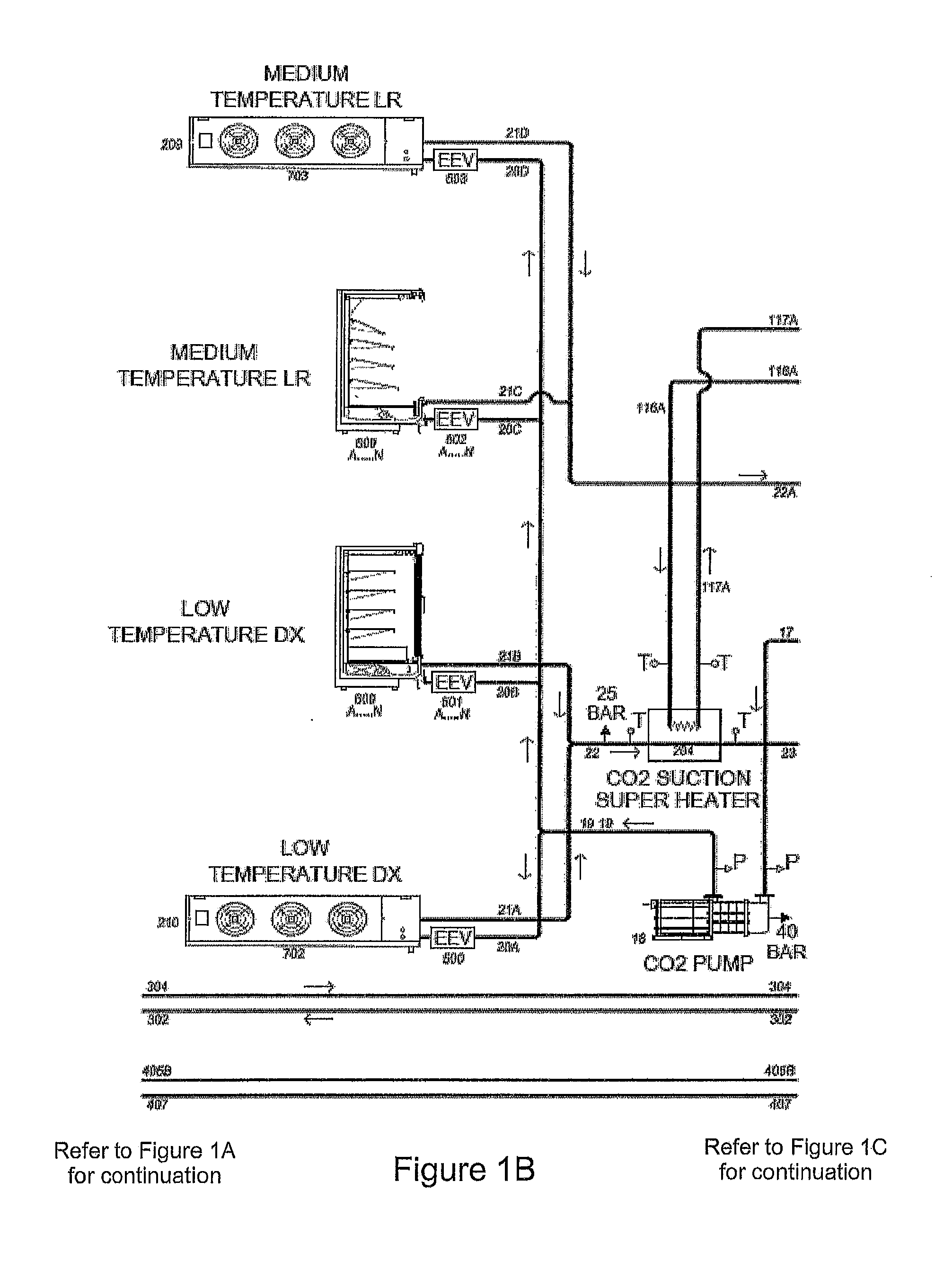
[0036]The invention will now be further illustrated with reference to the non limiting example depicted in the accompanying figure.

[0037]The low temperature segment (designated by 10 series of numbered components) operated in a closed cycle conventional vapour compressor refrigeration will have CO2 as the refrigerant and use a single or plurality of positive displacement type of compression system (10). The discharge gas of this compressor is directly led into the vapour line of CO2 entering the cascade heat exchangers (200 and 201). This vapour line not only receives the vapour from these compressors (13A and 13B), but also from the vapour space of the CO2 receiver (14A and 14B). An important requirement is that the CO2 liquid receiver (16) pressure (p16) must be matched with the discharge pressure (p13) of the compressor. Notionally, this pressure will be the saturation pressure of CO2 at the cascading temperature which is typically set at −7° C. in the description without prejudi...


PUM


Abstract

An integrated refrigeration and air conditioning plant working with environmentally friendly natural refrigerant carbon dioxide (CO2) and an ozone friendly non CO2 refrigerant. The low temperature refrigeration is provided by evaporating CO2 and the fluid is used as a secondary refrigerant, predominantly in liquid mode, for medium temperature refrigeration. The heat rejection from CO2 occurs to another upper stage cascaded refrigeration system that operates with a ozone friendly non CO2 refrigerant. Since air conditioning applications require cooling at temperatures higher than refrigeration for food sector, cooling for this range is derived from the non CO2 refrigerant.

Description

FIELD OF INVENTION[0001]The invention relates to refrigeration and air conditioning systems, including such systems when used in a supermarket setting. It specifically addresses the lacuna in integrating seemingly different, but intricately related, domains of cooling requirements at various temperature levels. The objectives are sought to be achieved in a manner that is environmentally friendly, energy efficient and operated in an intelligent way that marries the thermodynamic, fluid dynamic interface at two different refrigerants.BACKGROUND TO THE PRESENT INVENTION[0002]In this document the numbering of refrigerants is in accordance with the protocol recommended by the learned societies relevant to the profession of refrigeration and air conditioning, such as American Society of Refrigeration, Heating and Air conditioning Engineers (ASHRAE), International Institute of Refrigeration (IIR), Australian Institute of Refrigeration, Air Conditioning and Heating (AIRAH), Japan Society of...

Claims


Application Information

Patent Timeline
IPC IPC(8): F25B9/00
CPCF25B9/008F25B7/00F25B2309/06F25B2400/22
Inventor CONJEEVARAM, SARATHYSHEAHEN, PAULVISSER, MICHAELKANDADAI, SRINIVASAN
Owner CITY HLDG AUS
Why Eureka
Try Eureka