Automatic purging device for ac condensation drain lines

a technology of automatic purging and condensate drain line, which is applied in the direction of lighting and heating apparatus, heating types, transportation and packaging, etc., can solve the problems of clogging of drain lines, inability to call an ac specialist, and inability to predict the timing of clogging drain lines, etc., and achieves the effect of convenient replacement by consumers

Inactive Publication Date: 2013-11-21
DRAIN SHIELD
View PDF4 Cites 11 Cited by
  • Summary
  • Abstract
  • Description
  • Claims
  • Application Information

AI Technical Summary

Benefits of technology

[0018]An objective of the invention is to provide an automatic and reliable device for purging condensation lines by use of a disposable gas canister.
[0020]Still another objective of the invention is to provide a device that employs conventional and disposable gas cylinders that can be easily replaced by the consumer.
[0021]Still another objective of the invention is to provide a device for purging condensation lines which present minimal risk of further damage to the premises or to the drain lines.
[0023]Still another objective of the invention is to provide a device that can clear drain lines have poor draining characteristics due to excessive bends, lack of proper fluid slope, or the like.

Problems solved by technology

Unfortunately, over a period of time the drain line may become clogged due to algae, fungus, airborne debris entering the line, house settling, and so forth.
The occupant of the premise will understand that the air conditioner is not working resulting in a call to an AC specialist.
The timing of a clogged drain line cannot be predicted, but happenstance typically calls for the failure to occur at the least convenient time for the occupant.
Unfortunately HVAC service people are typically the busiest at such time, reducing the possibility of a timely service call which can aggravate an already unpleasant experience.
If the pressurized line is not properly installed leakage can occur right at the point of entry.
A p-trap may have been installed allowing the repair from a particular area, however, in many instances the p-trap is the location of the clog.
A low pressure flush may be inadequate and a high pressure flush may rupture the drain lines.

Method used


Image

  • Automatic purging device for ac condensation drain lines
  • Automatic purging device for ac condensation drain lines
  • Automatic purging device for ac condensation drain lines

Examples


Embodiment Construction

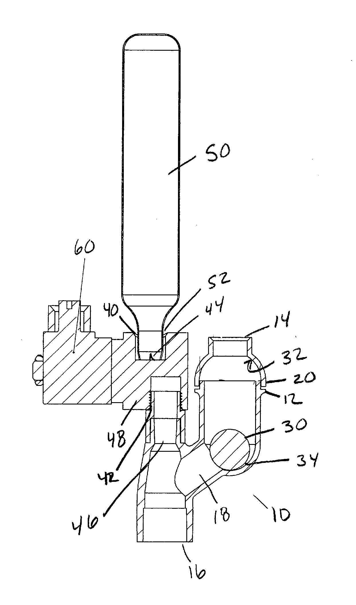
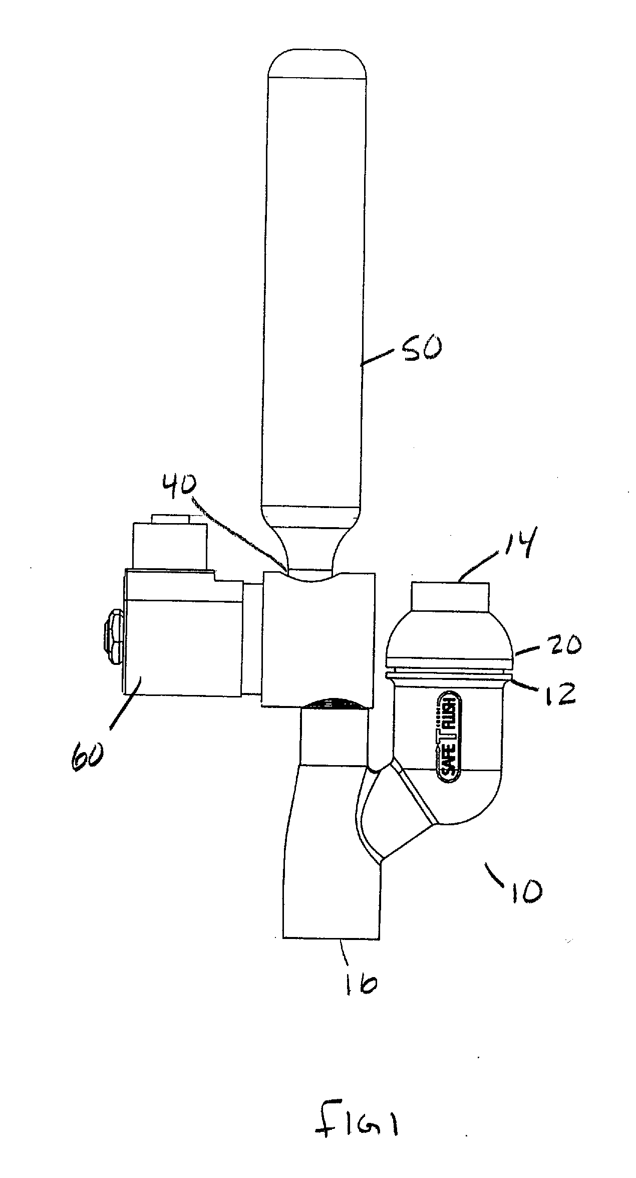
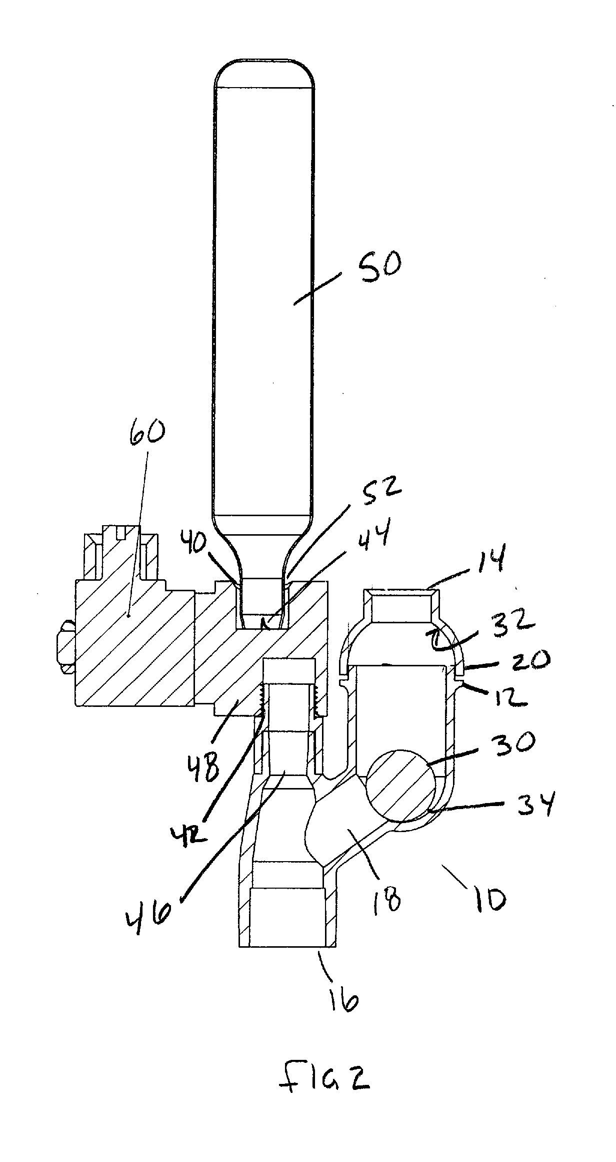
[0028]Now referring to the figures in general, set forth is the automatic in-line condensate drain purge device 10 of the instant invention. The device consists of a flow through housing 12 having a condensate inlet 14 and an outlet 16. The condensate inlet 14 is fluidly connected to the outlet 16 by a chamber 18 which allows normal condensate draining from the condensate inlet 13 to the outlet 16. The housing 12 is placed in-line with a new or preexisting condensate drain line. HVAC systems are heavily regulated and conventional code requires the air conditioner drain line to be white PVC pipe, the housing 12 is preferably made out PVC with the condensate inlet 14 and outlet 16 sized for an in-line direct coupling to the drain line allowing ease of installation. While glued PVC is preferable, the housing may also be threaded for compatibility. Further, the housing may have a threaded inlet and outlet wherein a PVC adapter may be employed to couple the threaded housing to a PVC pipe...


PUM


Abstract

An automatic condensate line purging device for HVAC condensation lines using pressurized gas. The purging device is installed in the condensate drain line of an air conditioning system allowing condensate flow through the device during normal operation where no clog has occurred in the condensate drain line. Should the drain line become clogged, a plug is displaced to seal the condensate drain causing the condensate to back-up up into the external condensate drain pan located beneath the condenser of conventional HVAC systems. When the drain pan fills with water, the safety float switch used to shut down the air conditioner is coupled to a solenoid valve mounted on the purging device wherein a charge of gas is directed into the drain line for removal of the clog.

Description

PRIORITY CLAIM[0001]This application is based upon and claims the priority date of U.S. Provisional Patent Application No. 61 / 648,812, entitled “AUTOMATIC PURGING DEVICE FOR AC CONDENSATION DRAIN LINES”, filed May 18, 2012, the contents of which is incorporated herein by reference.FIELD OF THE INVENTION[0002]This invention relates to the field of HVAC equipment and in particular to an automatic purging device for use with AC condensate drain lines.BACKGROUND OF THE INVENTION[0003]Conventional air conditioner systems utilize a drain pan for collection and removal of condensation. Condensation is the water formed on the evaporator coil during the air conditioning process. A drain pan is situated below the evaporator coil to collect the condensate and direct the condensate fluid to a drain, via a condensate drain line. Unfortunately, over a period of time the drain line may become clogged due to algae, fungus, airborne debris entering the line, house settling, and so forth. If a drain ...

Claims


Application Information

Patent Timeline
Patent Type & Authority Applications(United States)
IPC IPC(8): B08B5/02
CPCB08B5/02B08B9/0328F24F13/222Y10T137/4259Y10T137/3127Y10T137/8326Y10T137/4238Y10T137/7358F28F17/005
Inventor HUBBARD, SR., AUSTIN J.WINTER, LOUISA E.
Owner DRAIN SHIELD
Why Eureka
Try Eureka