High voltage inductor filter apparatus and method of use thereof

a filter apparatus and high-voltage technology, applied in the direction of inductance, circuit arrangement, core/yoke, etc., can solve the problems of overheating of the cables and any associated devices, such as motors, and severe increase in ac resistance of cables

Active Publication Date: 2013-11-21
CTM MAGNETICS
View PDF2 Cites 27 Cited by
  • Summary
  • Abstract
  • Description
  • Claims
  • Application Information

AI Technical Summary

Benefits of technology

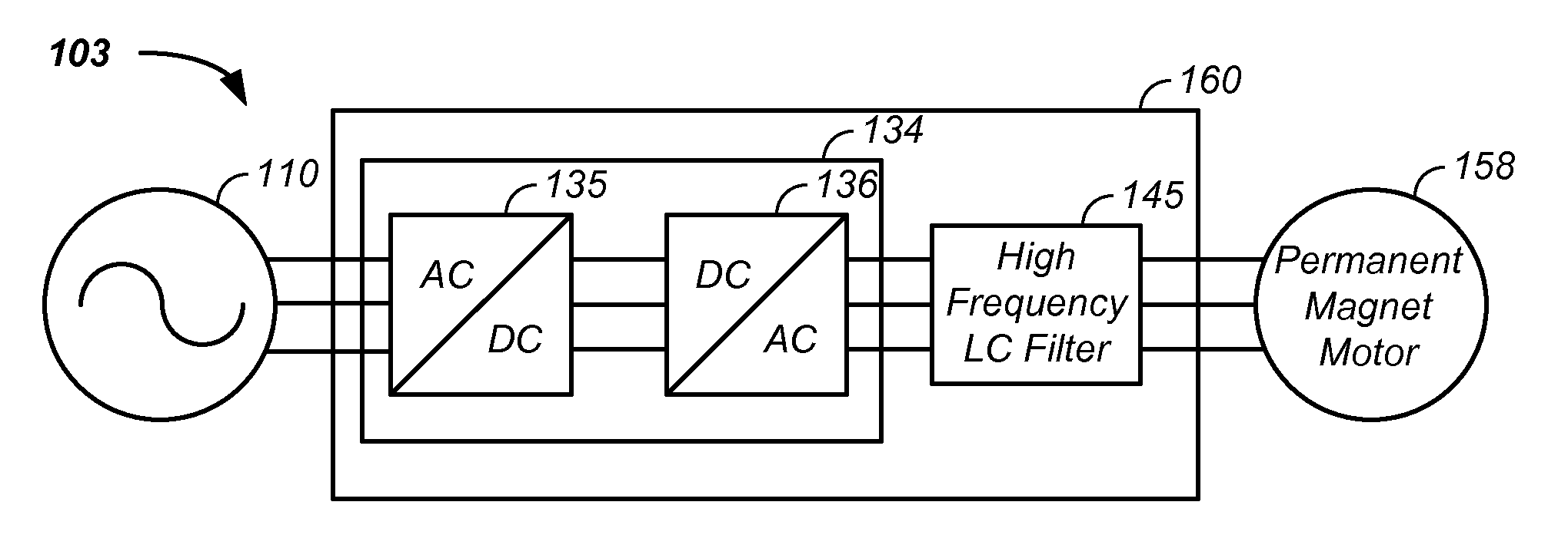
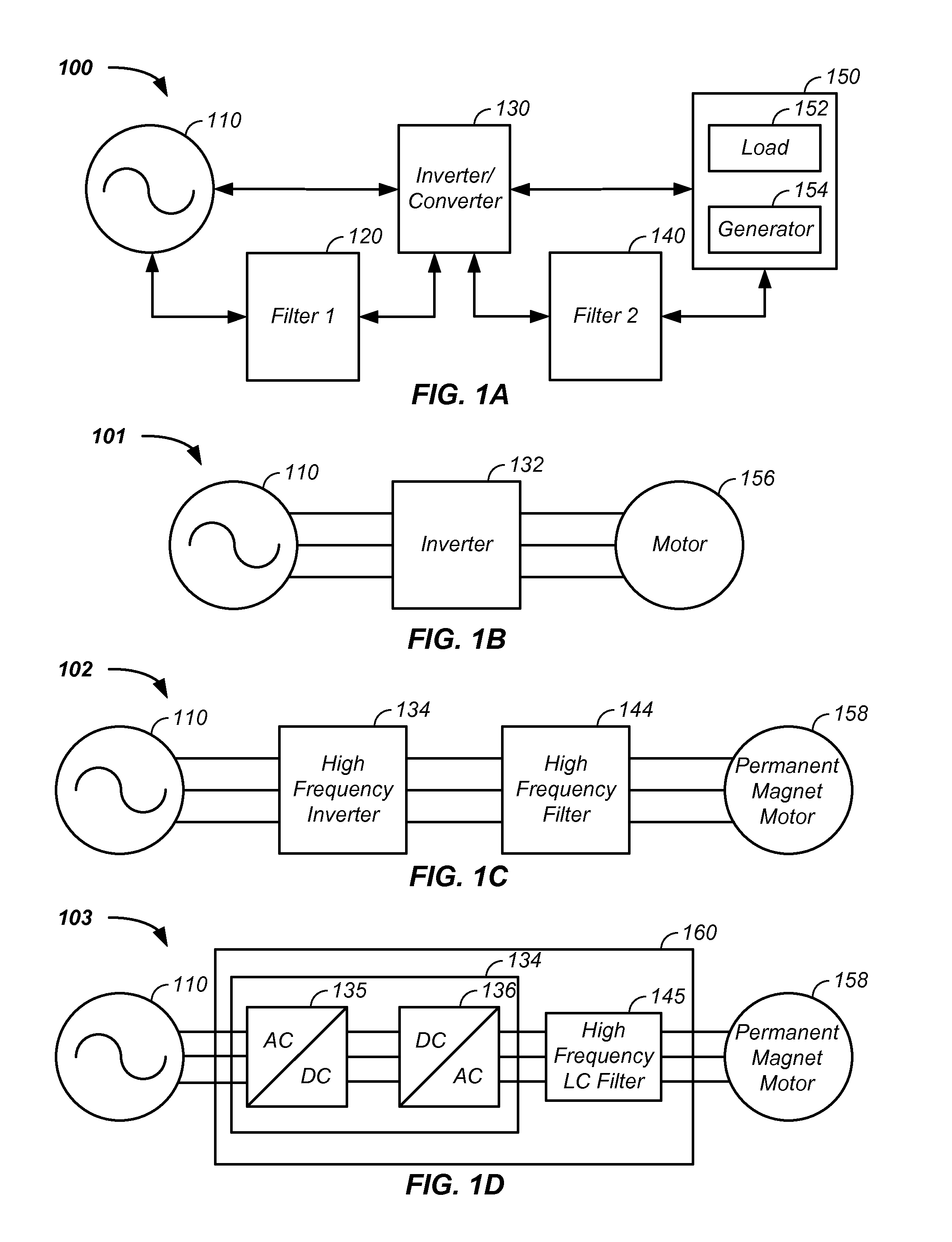
[0018]The invention comprises a high frequency filter coupled to an inverter apparatus having a high frequency output and method of use thereof.

Problems solved by technology

When frequencies in the 50-100 kHz range are added to the current spectrum, the industrial power cables overheat because of the high frequency travels only on the outside diameter of the conductor causing a severe increase in AC resistance of the cable and resultant overheating of the cables and any associated device, such as a motor.

Method used


Image

  • High voltage inductor filter apparatus and method of use thereof
  • High voltage inductor filter apparatus and method of use thereof
  • High voltage inductor filter apparatus and method of use thereof

Examples


Embodiment Construction

[0042]The invention comprises an inductor filter apparatus and method of use thereof.

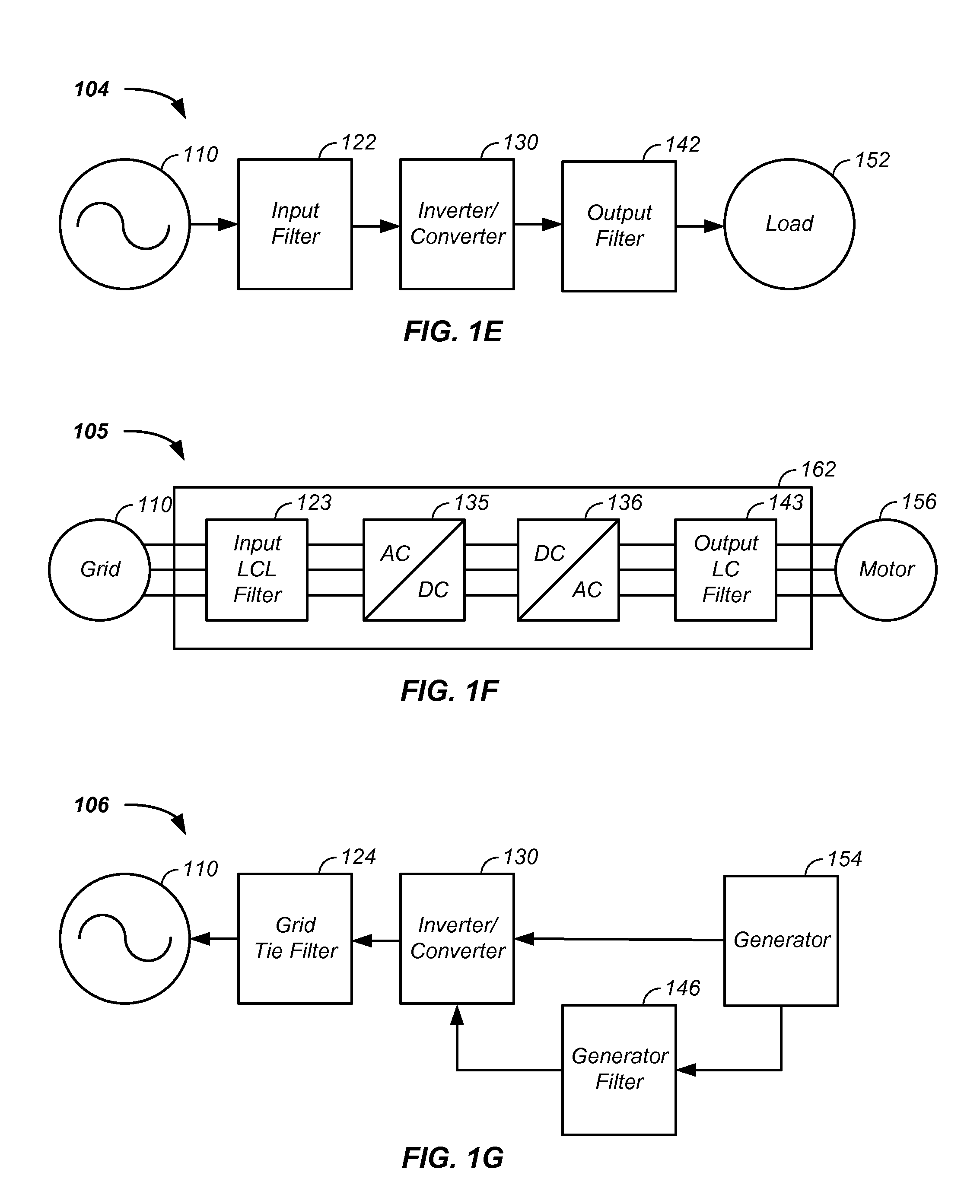
[0043]In one embodiment, an inverter and / or an inverter converter system yielding high frequency harmonics, referred to herein as a high frequency inverter, is coupled with a high frequency filter to yield clean power, reduced high frequency harmonics, and / or an enhanced energy processing efficiency system. In one case, a silicon carbide insulated gate bipolar transistors (IGBT) is used in the conversion of power from the grid and the IGBT outputs current, voltage, energy, and / or high frequency harmonics greater than 60 Hz to an output filter, such as a distributed gap inductor, which filters the output of the IGBT. In one illustrative example, a high frequency inductor and / or converter apparatus is coupled with a high frequency filter system, such as an inductor linked to a capacitor, to yield non-sixty Hertz output. In another illustrative example, an inductor / converter apparatus using a silicon c...


PUM


Abstract

The invention comprises a high frequency inductor filter apparatus coupled with an inverter yielding high frequency harmonics and/or non-sixty Hertz output. For example, an inductor/converter apparatus is provided that uses a silicon carbide transistor to output power having a carrier frequency, modulated by a fundamental frequency, and a set of harmonic frequencies. A filter, comprising an inductor having a distributed gap core material and optional magnet wires, receives power output from the inverter/converter and processes the power by passing the fundamental frequency while reducing amplitude of the harmonic frequencies.

Description

CROSS REFERENCES TO RELATED APPLICATIONS[0001]This application:[0002]is a continuation-in-part of U.S. patent application Ser. No. 13 / 470,281 filed May 12, 2012, which is a continuation-in-part of U.S. patent application Ser. No. 13 / 107,828 filed May 13, 2011, which[0003]is a continuation-in-part of U.S. patent application Ser. No. 12 / 098,880 filed Apr. 4, 2008, which[0004]claims benefit of U.S. provisional patent application No. 60 / 910,333 filed Apr. 5, 2007; and[0005]is a continuation-in-part of U.S. patent application Ser. No. 11 / 156,080 filed Jun. 15, 2005 (now U.S. Pat. No. 7,471,181), which claims benefit of U.S. provisional patent application No. 60 / 580,922 filed Jun. 17, 2004;[0006]is a continuation-in-part of U.S. patent application Ser. No. 12 / 197,034 filed Aug. 22, 2008, which claims benefit of U.S. provisional patent application No. 60 / 957,371, filed on Aug. 22, 2007; and[0007]is a continuation-in-part of U.S. patent application Ser. No. 12 / 434,894 filed Aug. 2, 2010, wh...

Claims


Application Information

Patent Timeline
Patent Type & Authority Applications(United States)
IPC IPC(8): H02M1/12
CPCH02M1/126H01F17/062H01F27/02H01F27/027H01F27/263H01F2038/006H02M5/458H01F3/14H01F27/085H01F27/255H01F27/266H01F27/2895H01F27/306Y02B70/10H05K3/303H05K7/10H02M1/12
Inventor MACLENNAN, GRANT A.
Owner CTM MAGNETICS
Why Eureka
Try Eureka