Systems and methods for vagal nerve stimulation

a vagal nerve and system technology, applied in the field of vagal nerve stimulation, can solve the problems of difficult, if not impossible, to provide treatment with a vagal nerve stimulator that is not implanted on the nerv

Active Publication Date: 2013-11-21
ELECTROCORE
View PDF17 Cites 64 Cited by
  • Summary
  • Abstract
  • Description
  • Claims
  • Application Information

AI Technical Summary

Benefits of technology

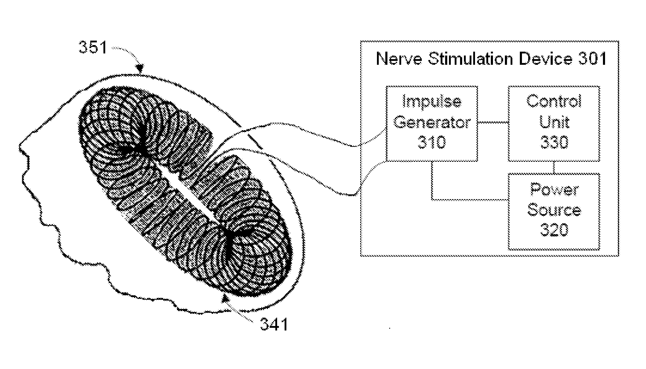
[0021]A source of power supplies a pulse of electric charge to the electrodes or magnetic stimulator coil, such that the electrodes or magnetic stimulator produce an electric current and / or an electric field within the patient. The electrical or magnetic stimulator is configured to induce a peak pulse voltage sufficient to produce an electric field in the vicinity of a nerve such as a vagus nerve, to cause the nerve to depolarize and reach a threshold for action potential propagation. By way of example, the threshold electric field for stimulation of the nerve may be about 8 V / m at 1000 Hz. For example, the device may produce an electric field within the patient of about 10 to about 600 V / m (preferably less than about 100 V / m) and an electrical field gradient of greater than about 2 V / m / mm. Electric fields that are produced at the vagus nerve are generally sufficient to excite all myelinated A and B fibers, but not necessarily the unmyelinated C fibers. However, by using a reduced amplitude of stimulation, excitation of A-delta and B fibers may also be avoided.
[0022]The preferred stimulator shapes an elongated electric field of effect that can be oriented parallel to a long nerve, such as a vagus. By selecting a suitable waveform to stimulate the nerve, along with suitable parameters such as current, voltage, pulse width, pulses per burst, inter-burst interval, etc., the stimulator produces a correspondingly selective physiological response in an individual patient. Such a suitable waveform and parameters are simultaneously selected to avoid substantially stimulating nerves and tissue other than the target nerve, particularly avoiding the stimulation of nerves in the skin that produce pain.

Problems solved by technology

Unfortunately, this not only involves a continuous drain on the power supply of the vagal nerve stimulator, but it makes it very difficult, if not impossible, to provide treatment with a vagal nerve stimulator that is not implanted on the nerve.

Method used


Image

  • Systems and methods for vagal nerve stimulation
  • Systems and methods for vagal nerve stimulation
  • Systems and methods for vagal nerve stimulation

Examples


Embodiment Construction

[0052]In some embodiments, numbers expressing frequencies, periods of time, or quantities or levels of current, voltage, energy, and so forth, used to describe and claim certain embodiments of the present disclosure are to be understood as being modified in some instances by the term “about.” In some embodiments, the term “about” is used to indicate that a value includes the standard deviation of the mean for the device or method being employed to determine the value. In some embodiments, the numerical parameters set forth in the written description and attached claims are approximations that can vary depending upon the desired properties sought to be obtained by a particular embodiment. In some embodiments, the numerical parameters should be construed in light of the number of reported significant digits and by applying ordinary rounding techniques. Notwithstanding that the numerical ranges and parameters setting forth the broad scope of some embodiments of the present disclosure a...


PUM


Abstract

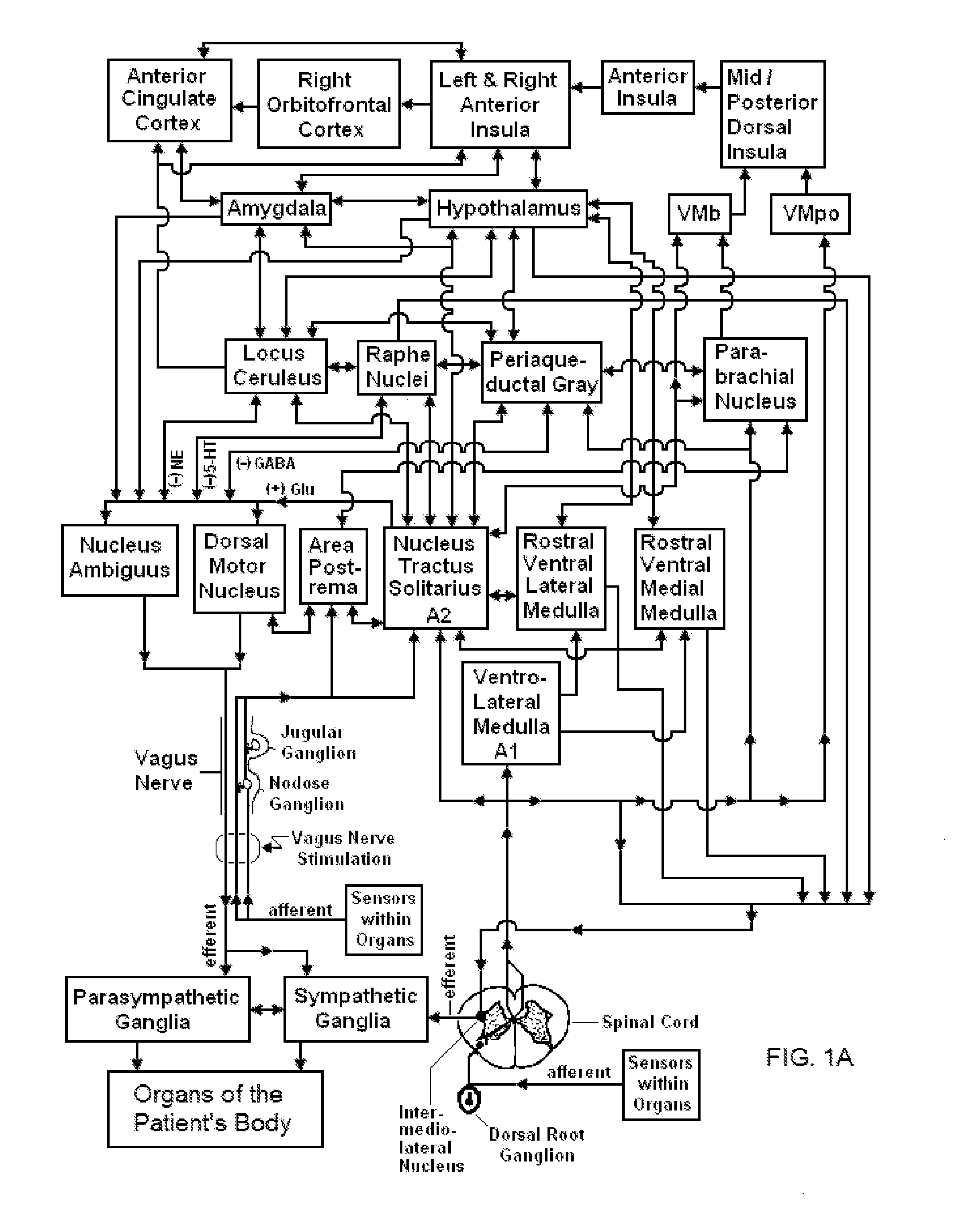
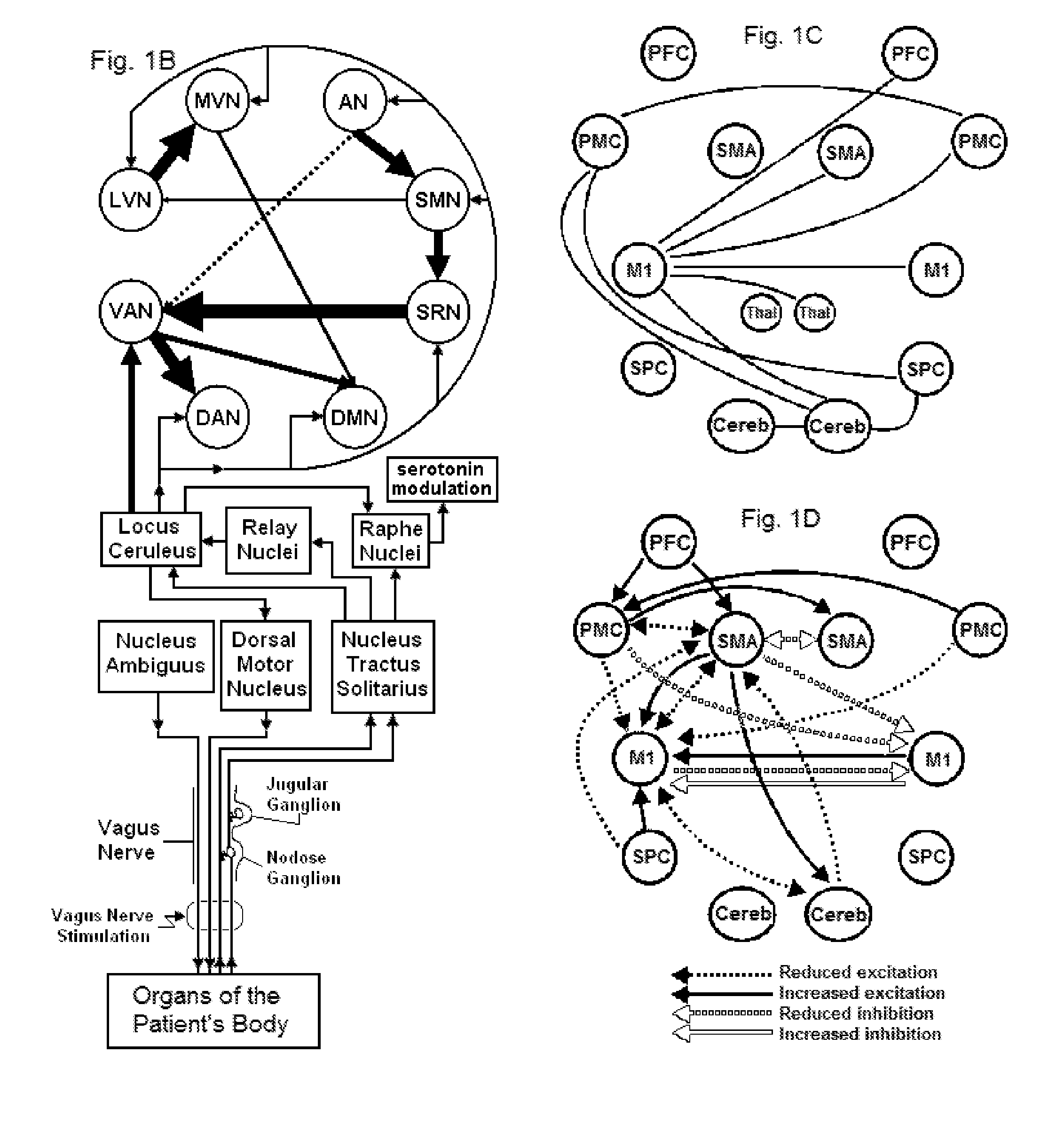
Devices, systems and methods are disclosed for electrical stimulation of the vagus nerve to treat or prevent disorders in a patient. The methods comprise transmitting impulses of energy to the vagus nerve according to a treatment paradigm that includes single doses of 30 seconds to 5 minutes of continuous stimulation. The treatment paradigm further comprises one or more daily treatment sessions that each include one or more doses for prophylactic or acute treatment of the patient's condition. Vagus nerve stimulation is used to modulate the release of inhibitory neurotransmitters in the brain, such as GABA, norepinephrine, and/or serotonin.

Description

CROSS REFERENCE TO RELATED APPLICATIONS[0001]This application is a Continuation in Part of U.S. patent application Ser. No. 13 / 603,781 filed Sep. 5, 2012; which is a Continuation in Part of U.S. patent application Ser. No. 13 / 222,087 filed Aug. 31, 2011; which is a Continuation in Part of U.S. patent application Ser. No. 13 / 183,765 filed Jul. 15, 2011; which is a Continuation in Part of U.S. patent application Ser. No. 13 / 183,721 filed Jul. 15, 2011; which claims the benefit of priority to U.S. Provisional Application No. 61 / 488,208 filed May 20, 2011 and U.S. Provisional Application No. 61 / 487,439 filed May 18, 2011.[0002]This application also is a Continuation in Part of U.S. patent application Ser. No. 13 / 109,250 filed May 17, 2011; which claims the benefit of priority to U.S. Provisional Application No. 61 / 471,405 filed Apr. 4, 2011.[0003]This application also is a Continuation in Part of U.S. patent application Ser. No. 13 / 075,746 filed Mar. 30, 2011; which claims the benefit o...

Claims


Application Information

Patent Timeline
Patent Type & Authority Applications(United States)
IPC IPC(8): A61N1/05
CPCA61N1/0551A61B5/4836A61N1/0456A61N1/36025A61N1/36053A61N2/006A61N2/008A61N2/02A61B5/369
Inventor SIMON, BRUCE J.ERRICO, JOSEPH P.
Owner ELECTROCORE
Why Eureka
Try Eureka