
Arrangement and method for model-based testing

Inactive Publication Date: 2013-11-21
TEKNOLOGIAN TUTKIMUSKESKUS VTT
View PDF3 Cites 44 Cited by
  • Summary
  • Abstract
  • Description
  • Claims
  • Application Information

AI Technical Summary

Benefits of technology

The objective of this patent is to provide a solution for at least partly automated analysis of test results conducted in connection with model-based testing to facilitate failure detection and cause tracking such as root cause tracking. The invention is based on a rule and database based analysis framework that allows detection of complex failures caused by multiple atomic occurrences. Maintaining a local database or other memory entity regarding the failures detected enables the detection of repeating failures, and the analysis may be performed faster and more reliably with automated decision-making. The invention offers flexible analysis scope, reduces burden in the integration of new or changing tools in the testing environment, and may apply a plurality of different interfaces to input and output the data as desired.

Problems solved by technology

Traditionally, testing of software and related products, such as network elements and terminals in the context of communication systems, has been a tedious process providing somewhat dubious results.
However, in practice high level automatization has turned out to be rather difficult in conjunction with the more complex SUTs.
With complex SUTs that may utilize e.g. object oriented programming code and involve multiple parallel threads, digging up the core cause of a failed test may just be in many occasions impossible from the standpoint of a human tester.
Such a root cause is not unambiguously traceable due to the excessive amount of information to be considered.
For example, in connection with 2G and 3G cellular networks system testing, e.g. MSS (Mobile Switching Centre Server) testing or testing of other components, problematic events such as error situations do not often materialize as unambiguous error messages.
The manual analysis of the available log file may turn out extremely intricate as the MSS and many other components transmit and receive data in several threads certainly depending on the particular implementation in question, which renders the analysis task both tricky and time-consuming.
Further, different infrastructural surveillance systems are prone to malfunctions and misuse, which cause the systems to operate defectively or may render the whole system out of order.
The infrastructural surveillance systems often reside in remote locations, which cause the maintenance to be expensive and slow.

Method used


Image

  • Arrangement and method for model-based testing
  • Arrangement and method for model-based testing
  • Arrangement and method for model-based testing

Examples


Embodiment Construction

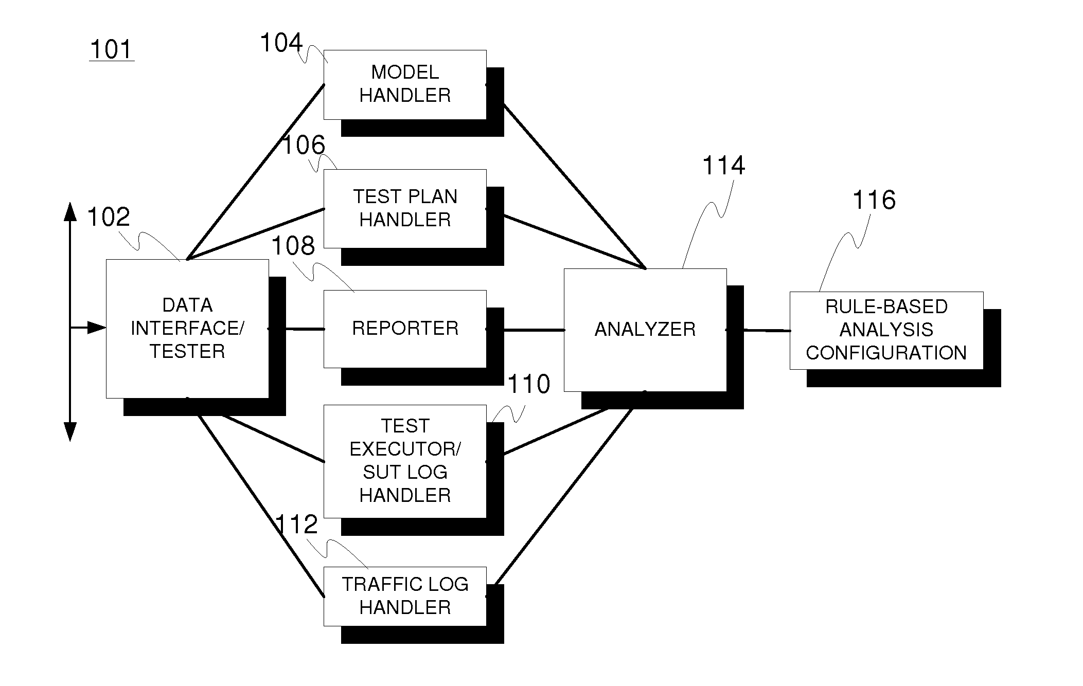
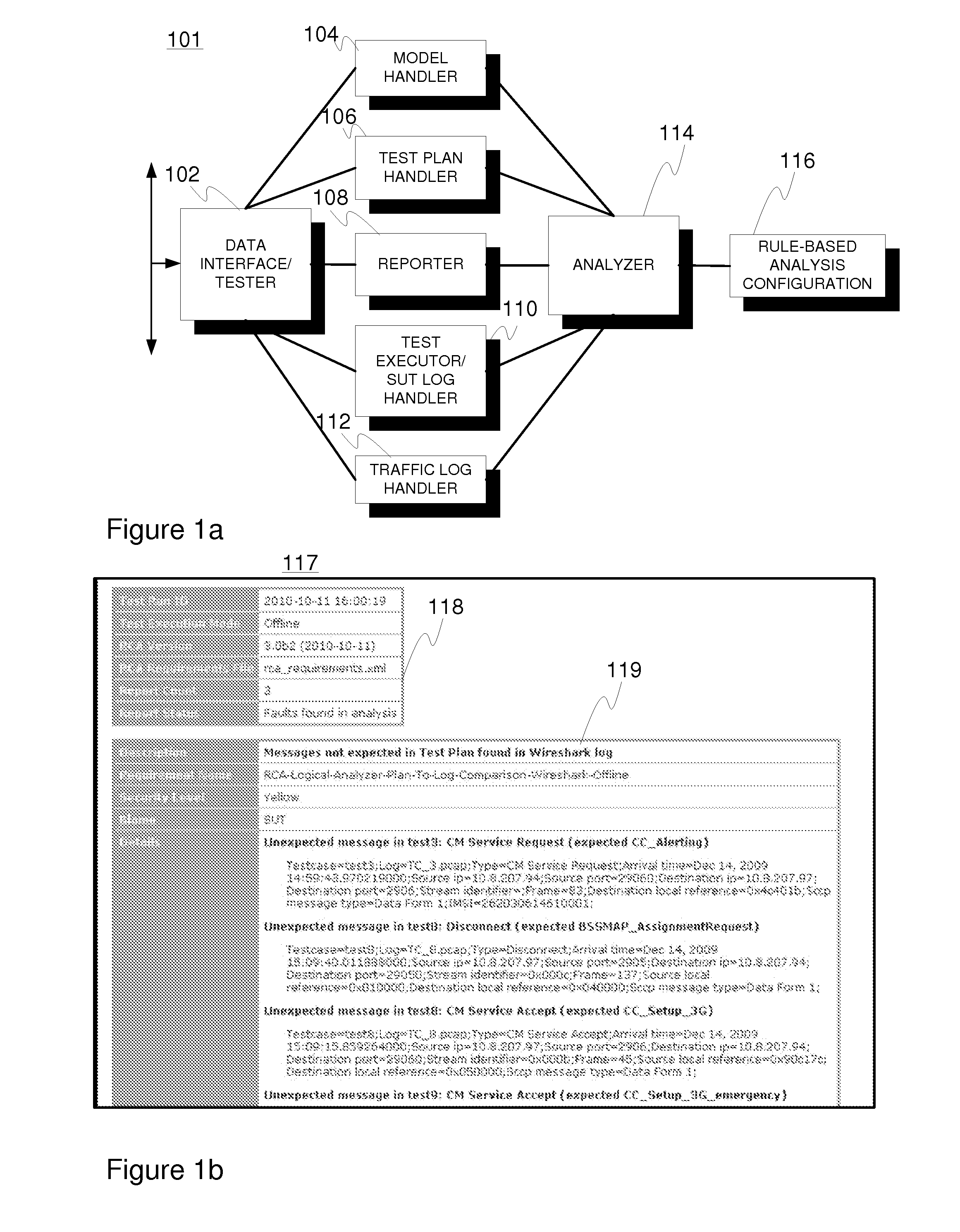
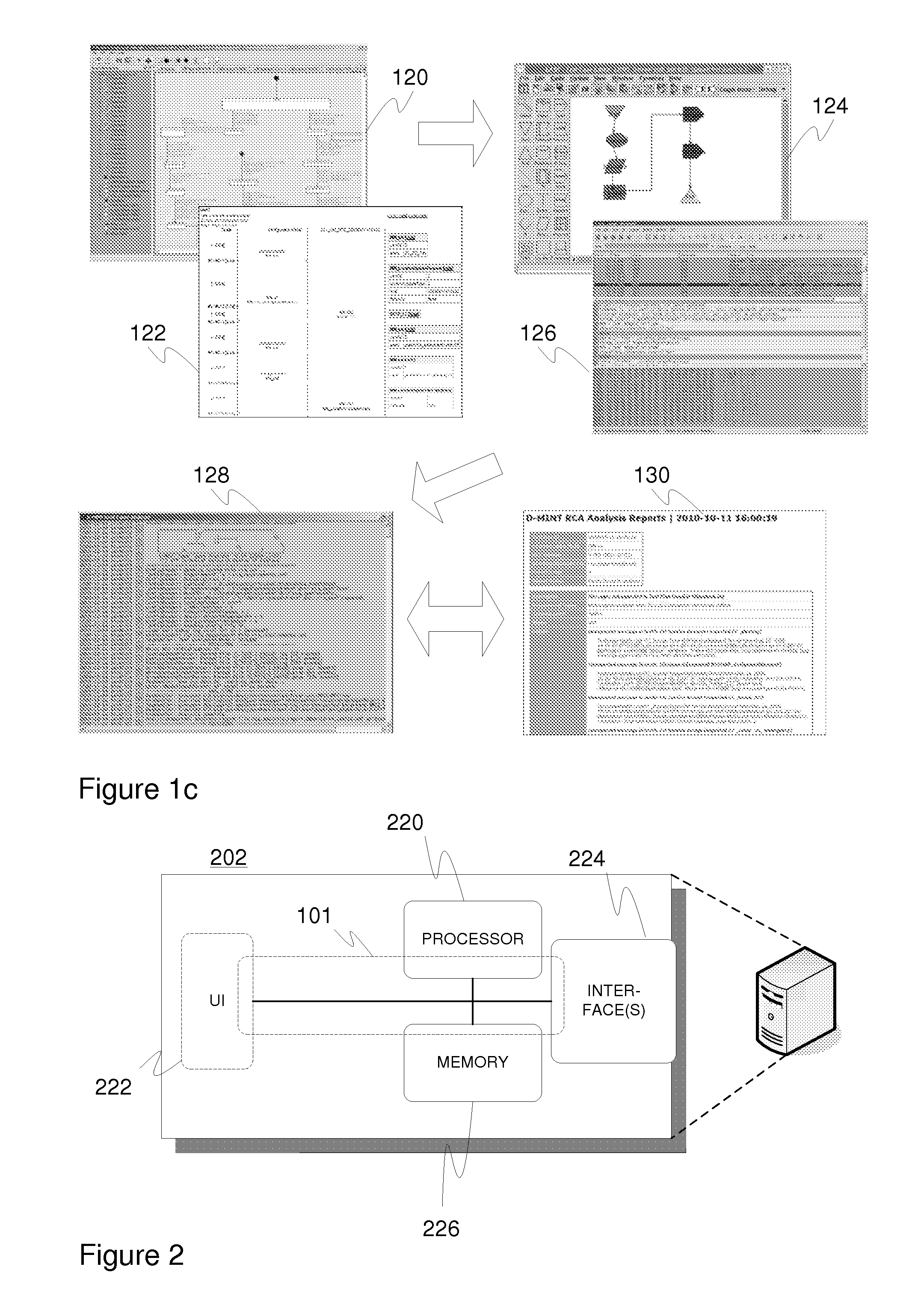
[0066]FIG. 1a depicts a block diagram of an embodiment 101 of the proposed arrangement. As described hereinbefore, the suggested division of functionalities between different entities is mainly functional (logical) and thus the physical implementation may include a number of further entities constructed by splitting any disclosed one into multiple ones and / or a number of integrated entities constructed by combining at least two entities together. The disclosed embodiment is intended for use with offline testing / execution, but the fulcrum of the present invention is generally applicable for online use as well.

[0067]Data interface / tester 102 may refer to at least one data interface entity and / or testing entity (test executor) providing the necessary external input data such as model, test case and log data to the other entities for storage, processing, and / or analysis, and output data such as analysis reports back to external entities. In some embodiments, at least part of the functio...


PUM


Abstract

An electronic arrangement for analyzing a model-based testing scenario relating to a system under test (SUT), includes a model handler entity for obtaining and managing model data indicative of a model intended to exhibit the behavior of the SUT, a test plan handler entity for obtaining and managing test plan data indicative of a number of test cases relating to the model and expected outcome thereof, a test execution log handler entity for obtaining and managing test execution log data indicative of the execution of the test cases by the test executor and / or SUT, a communications log handler entity for obtaining and managing communications log data indicative of message traffic between the test executor entity and SUT, and an analyzer entity for detecting a number of failures and their causes in the model-based testing scenario on the basis of model, test plan, test execution log and communications log data.

Description

FIELD OF THE INVENTION[0001]Generally the present invention pertains to testing such as software testing. In particular, however not exclusively, various embodiments of the present invention are related to model-based testing and remote testing.BACKGROUND[0002]Software testing often refers to a process of executing a program or application in order to find software errors, i.e. bugs, which reside in the product. In more general terms, software testing may be performed to validate the software against the design requirements thereof and to find the associated flaws and peculiarities. Both functional and non-functional design requirements may be evaluated. Yet, the tests may be executed at unit, integration, system, and system integration levels, for instance. Testing may be seen as a part of the quality assurance of the tested entity.[0003]Traditionally, testing of software and related products, such as network elements and terminals in the context of communication systems, has been ...

Claims


Application Information

Patent Timeline
IPC IPC(8): G06F11/36H04L41/00H04L43/00
CPCG06F11/3688G06F11/3672H04L41/145H04L41/16H04L43/50G06F11/2252
Inventor NIEMINEN, MIKKORATY, TOMI
Owner TEKNOLOGIAN TUTKIMUSKESKUS VTT
Learn More