

Thermoelectric Apparatus And Applications Thereof
a technology of thermoelectric apparatus and thermoelectric materials, which is applied in the direction of thermoelectric devices, pv power plants, single-walled nanotubes, etc., can solve the problems of significant heat energy escape into the environment, about 15 terawatts of power loss to the environment, and low efficiency of converting heat energy into electrical energy by current methods, etc., to overcome or mitigate one or more disadvantages of current thermoelectric materials
- Summary
- Abstract
- Description
- Claims
- Application Information
AI Technical Summary
Benefits of technology
Problems solved by technology
Method used
Image

Examples
example 1
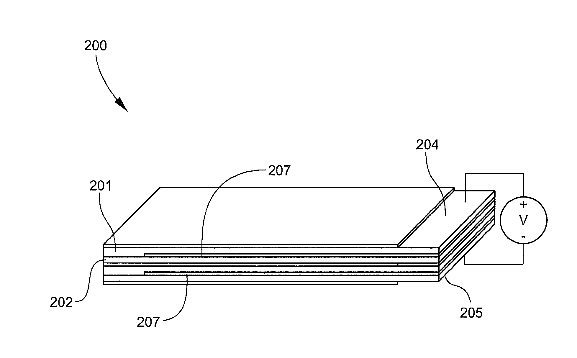
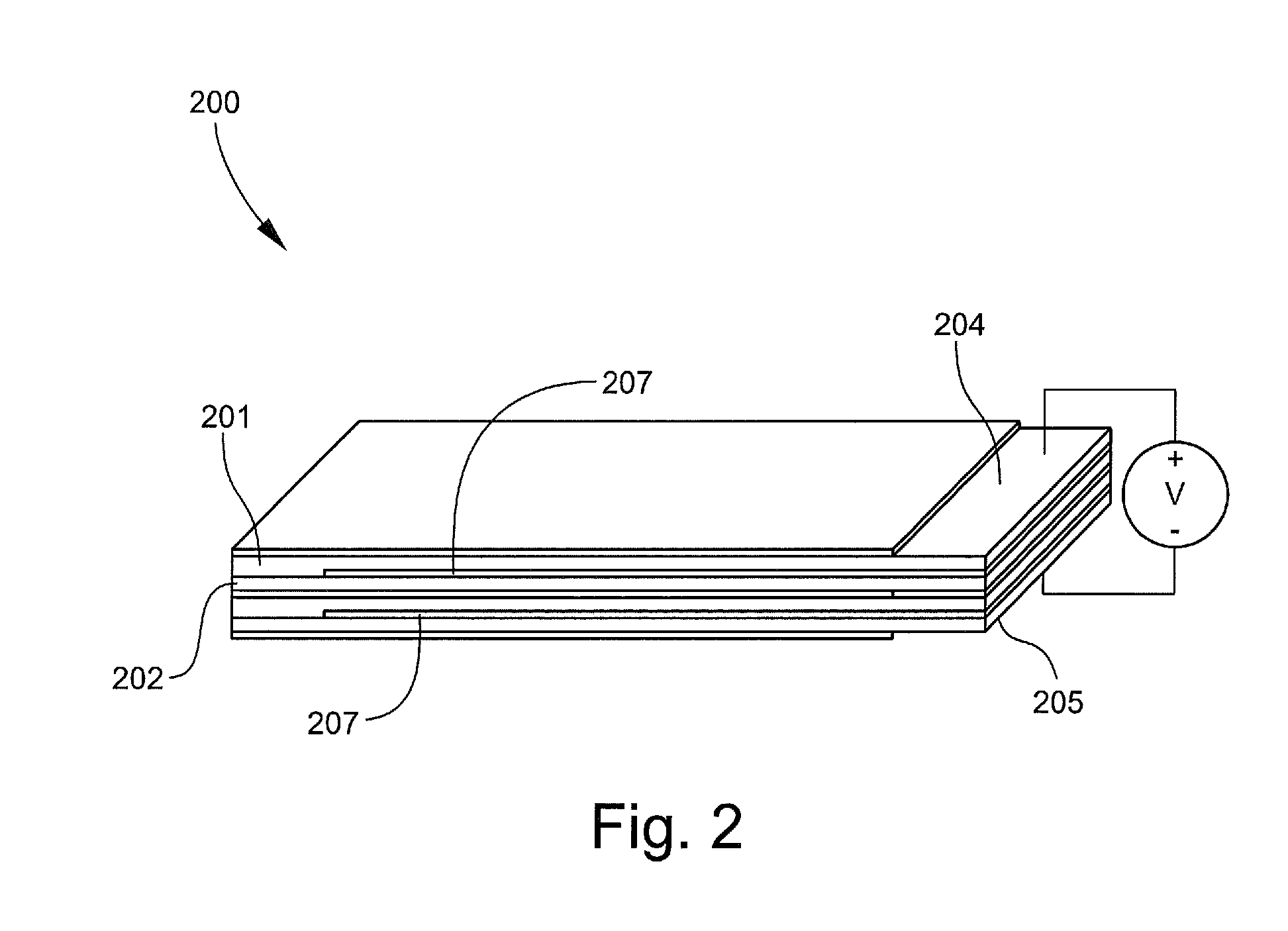
Thermoelectric Apparatus
[0123]A first p-type layer was fabricated by providing 35 mg of single-walled carbon nanotubes (SWNT) to which was added 17.5 ml of dimethylacrylamide (DMA). The resulting mixture was high energy sonicated for a period of one hour. Polyvinylidene fluoride (PVDF) was added to the mixture in an amount to render the SWNT 20 weight percent of the mixture on a total solids basis. The resulting SWNT / PVDF / DMA mixture was high energy sonicated for one hour.
[0124]A glass slide having dimensions of 75 mm×45 mm was cleaned in methanol and placed on a hot plate at 90° C. The SWNT / PVDF / DMA mixture was poured evenly onto the slide and the DMA was allowed to evaporate. The dried SWNT / PVDF film was placed into an oven at 100° C. for 12 hours to anneal. The slide was subsequently removed from the oven and methanol was poured over the SWNT / PVDF film. The SWNT / PVDF film was carefully removed from the glass slide, washed in deionized water and dried.
[0125]A second p-type layer w...
PUM
| Property | Measurement | Unit |
|---|---|---|
| Seebeck coefficient | aaaaa | aaaaa |
| thickness | aaaaa | aaaaa |
| Seebeck coefficient | aaaaa | aaaaa |
Abstract
Description
Claims
Application Information