
Touchscreen using both carbon nanoparticles and metal nanoparticles

a technology of carbon nanoparticles and metal nanoparticles, applied in the direction of conductors, instruments, transportation and packaging, etc., can solve the problems of touchscreen malfunction, failure, and/or function differently than intended, and may be relatively expensive, and achieve the effect of increasing the cost of the touchscreen

Active Publication Date: 2009-02-19
ELO TOUCH SOLUTIONS INC
View PDF21 Cites 36 Cited by
  • Summary
  • Abstract
  • Description
  • Claims
  • Application Information

AI Technical Summary

Benefits of technology

The patent text describes a cover sheet assembly and a substrate assembly for a touchscreen system. These assemblies include an insulating layer and an electrically conductive material made of carbon nanoparticles and metal nanoparticles. The technical effect of this invention is to provide a more efficient and reliable electrically conductive material for touchscreen systems that improves touch sensitivity and durability.

Problems solved by technology

However, ITO may be somewhat brittle such that the electrically conductive material may crack, fracture, and / or fatigue after repeated touches, which may cause the touchscreen to malfunction, fail, and / or function differently than intended.
Moreover, because the supply of indium is limited, ITO may be relatively expensive.
Increasing demand for indium may cause ITO to become even more expensive as the world supply diminishes.
However, metal nanofibers may be prone to atmospheric corrosion.
Atmospheric corrosion of metal nanofibers within the electrically conductive material may increase a contact resistance of the electrically conductive material, which may decrease the flow of electrical current into and out of the electrically conductive material at the point of contact between the electrically conductive material with another electrically conductive material.
However, carbon nanotubes may not match the transparency of ITO for a given electrical conductivity.

Method used


Image

  • Touchscreen using both carbon nanoparticles and metal nanoparticles
  • Touchscreen using both carbon nanoparticles and metal nanoparticles
  • Touchscreen using both carbon nanoparticles and metal nanoparticles

Examples


example

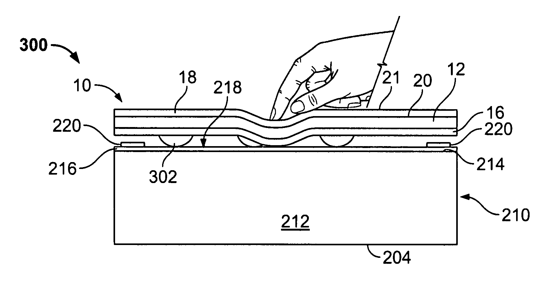
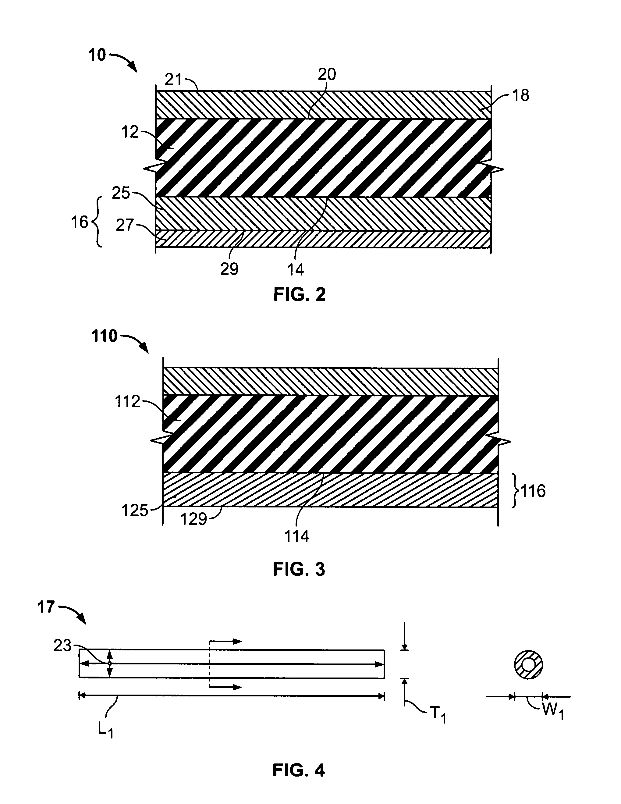
[0051]As described above, each layer of the electrically conductive materials described and illustrated herein may be fabricated using any suitable method, structure, process, and / or means that enables the layers to function as described herein. One example of fabricating the layers 25 and 27 (FIG. 2) includes, but is not limited to:[0052](1) generating the layer 27 by growing the carbon nanoparticles 17 in the pattern of the carbon nanoparticles 17 illustrated in FIG. 6 onto a quartz substrate by pyrolyzing iron (II) phthalocyanine (FePc) under an argon / hydrogen atmosphere at between approximately 800 and 1100° C. (see Yang, Y.; Huang, S.; He, H.; Mau, A. W. H.; Dai, L. J. Am. Chem. Soc. 1999, 121, 10832; and Dai, L.; Patil, A.; Gong, X.; Guo, Z.; Liu, L.; Liu, Y.; Zhu, D. Chem. Phys. Chem. 2003, 4, 1150, and references cited therein);[0053](2) functionalizing the carbon nanoparticles 17 by grafting a carboxylic group to the walls of the carbon nanoparticles 17 using polyacrylic ac...


PUM

PropertyMeasurementUnit
sheet resistanceaaaaaaaaaa
contact resistanceaaaaaaaaaa
lengthsaaaaaaaaaa

Abstract

A cover sheet assembly is provided for a touchscreen system. The cover sheet assembly includes an insulating layer having a surface configured to be disposed over an electrically conductive area of a substrate of the touchscreen system, and an electrically conductive material disposed on at least a portion of the surface of the insulating layer. The electrically conductive material includes a plurality of carbon nanoparticles and a plurality of metal nanoparticles.

Description

BACKGROUND OF THE INVENTION[0001]The invention relates generally to computer touchscreens, and more particularly, to electrically conductive materials for touchscreens.[0002]Since their introduction in the early 1970s, touchscreens have afforded alternatives to keyboards for certain computer applications. In many situations the keyboard and mouse are eliminated, because the touchscreen provides the user with access to the computer. Both resistive and capacitive touchscreens typically include a substrate, such as a glass panel, that is positioned over the face of a display, for example a liquid crystal display (LCD). The substrate includes an electrically conductive material on a surface thereof. The electrically conductive material defines an electrically conductive touch area on the substrate surface for accepting a user's inputs to the touchscreen. An insulating layer is positioned over the electrically conductive area to provide a surface for the user to touch to select the input...

Claims


Application Information

Patent Timeline
Patent Type & Authority Applications(United States)
IPC IPC(8): G06F3/041H01B5/00
CPCG06F3/045Y10T428/24994
Inventor PENNINGTON, BRIAN D.KENT, JOEL C.
Owner ELO TOUCH SOLUTIONS INC
Learn More