Display device, method for driving same, and electronic apparatus
a technology for display devices and electronic devices, applied in the direction of electric digital data processing, instruments, computing, etc., can solve problems such as power consumption of display devices, and achieve the effect of improving the accuracy of results and increasing the number of times external detection devices carry out detection
- Summary
- Abstract
- Description
- Claims
- Application Information
AI Technical Summary
Benefits of technology
Problems solved by technology
Method used
Image

Examples
embodiment 1
[0039]An embodiment of the present invention is described with reference to FIGS. 1 through 3, FIG. 9, and FIG. 19.
[0040](Configuration of an Electronic Apparatus 1)
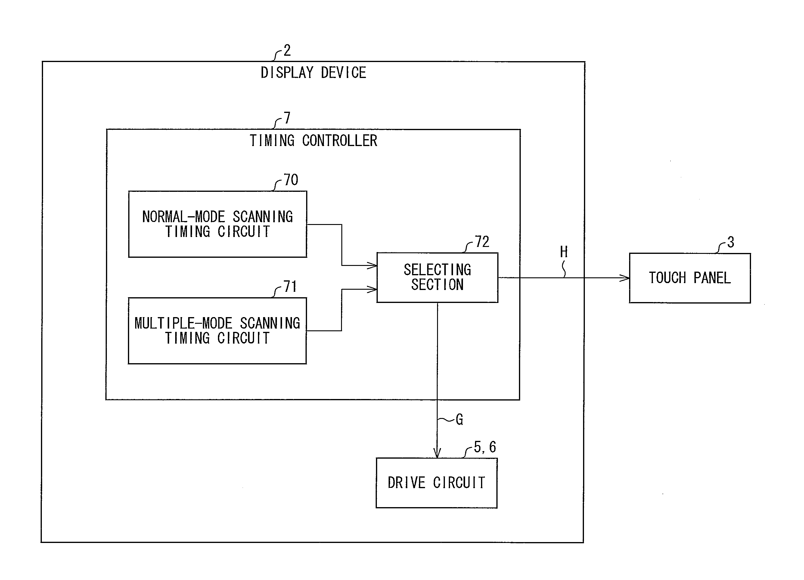
[0041]First, a configuration of an electronic apparatus 1 according to the present embodiment is described with reference to FIG. 9. FIG. 9 is a block diagram showing the configuration of the electronic apparatus 1 in detail. As shown in FIG. 9, the electronic apparatus 1 includes a display device 2, a touch panel 3, and a main device 10. In the electronic apparatus 1 of the present embodiment, the main device 10 outputs a video image to the display device 2 so that the display device 2 displays the video image, and the main device 10 obtains user's instructions via the touch panel 3 and carries out various processes in accordance with the user's instructions thus obtained. Note that the main device 10 may also output any information such as a still image or a symbol as well as a video image to the display device 2 so th...
embodiment 2
[0083]Another embodiment of the present invention is discussed with reference to FIG. 4. An electronic apparatus 1 of the present embodiment is identical to the electronic apparatus 1 shown in FIG. 1, except that when in a pause mode, the signal line drive circuit 5 has its driving performance lowered. Note that members which are similar in configuration and processing to the members described in Embodiment 1 are given the same reference signs, and as such, are not described below.
[0084]FIG. 4 is a timing chart showing temporal changes in operation status and signal status of the display device 2 of the present embodiment. Specifically, FIG. 4 shows a vertical sync signal, an operation status, and a state of driving performance of the signal line drive circuit 5, starting from the top. Note that when the driving performance is at a high level, the signal line drive circuit 5 is in a state in which to carry out normal driving and that when the driving performance is at a low level, t...
embodiment 3
[0086]Next, still another embodiment of the present invention is described with reference to FIG. 5. An electronic apparatus 1 of the present embodiment is identical to the electronic apparatus 1 shown in FIG. 1, except that (i) the display device 2 employs interlaced scanning as a way of scanning and (ii) the polarity of a data signal is inverted immediately before the display device 2 shifts from a first pause mode to a second scan mode. Note that members which are similar in configuration and processing to the members described in Embodiments 1 and 2 are given the same reference signs, and as such, are not described below.
[0087]FIG. 5 is a timing chart showing temporal changes in operation status and signal status of the display device 2 of the present embodiment. Specifically, FIG. 5 shows (i) a vertical sync signal, (ii) an operation status, (iii) a pause and drive control signal, (iv) scan signal to be outputted to the scan signal lines G, respectively, and (v) the polarity of...
PUM
 Abstract
Description
Claims
Application Information
 - R&D
- Intellectual Property
- Life Sciences
- Materials
- Tech Scout
- Unparalleled Data Quality
- Higher Quality Content
- 60% Fewer Hallucinations
Browse by: Latest US Patents, China's latest patents, Technical Efficacy Thesaurus, Application Domain, Technology Topic, Popular Technical Reports.
© 2025 PatSnap. All rights reserved.Legal|Privacy policy|Modern Slavery Act Transparency Statement|Sitemap|About US| Contact US: help@patsnap.com