Impeller manufacturing method

Active Publication Date: 2013-12-05
MITSUBISHI HEAVY INDUSTIES COMPRESSOR CORP
View PDF12 Cites 14 Cited by
  • Summary
  • Abstract
  • Description
  • Claims
  • Application Information

AI Technical Summary

Benefits of technology

The present invention aims to prevent defects in brazing materials and gaps at the brazing interface during the brazing process. This is achieved through controlling the temperature increasing rate during the brazing thermal cycle and providing an intermediate retention. Additionally, using a heating body placed during the brazing process can suppress the space between the brazing interface and inhibit defects in the brazing material. This results in a quick brazing thermal cycle and reduces the risk of defects.

Problems solved by technology

With a quenching process starting at a temperature slightly lower than that of the liquid phase of the brazing material, the strength of a brazed bonded part is insufficient, resulting in a crack in the brazed bonded part.

Method used


Image

  • Impeller manufacturing method
  • Impeller manufacturing method
  • Impeller manufacturing method

Examples


first embodiment

1. First Embodiment

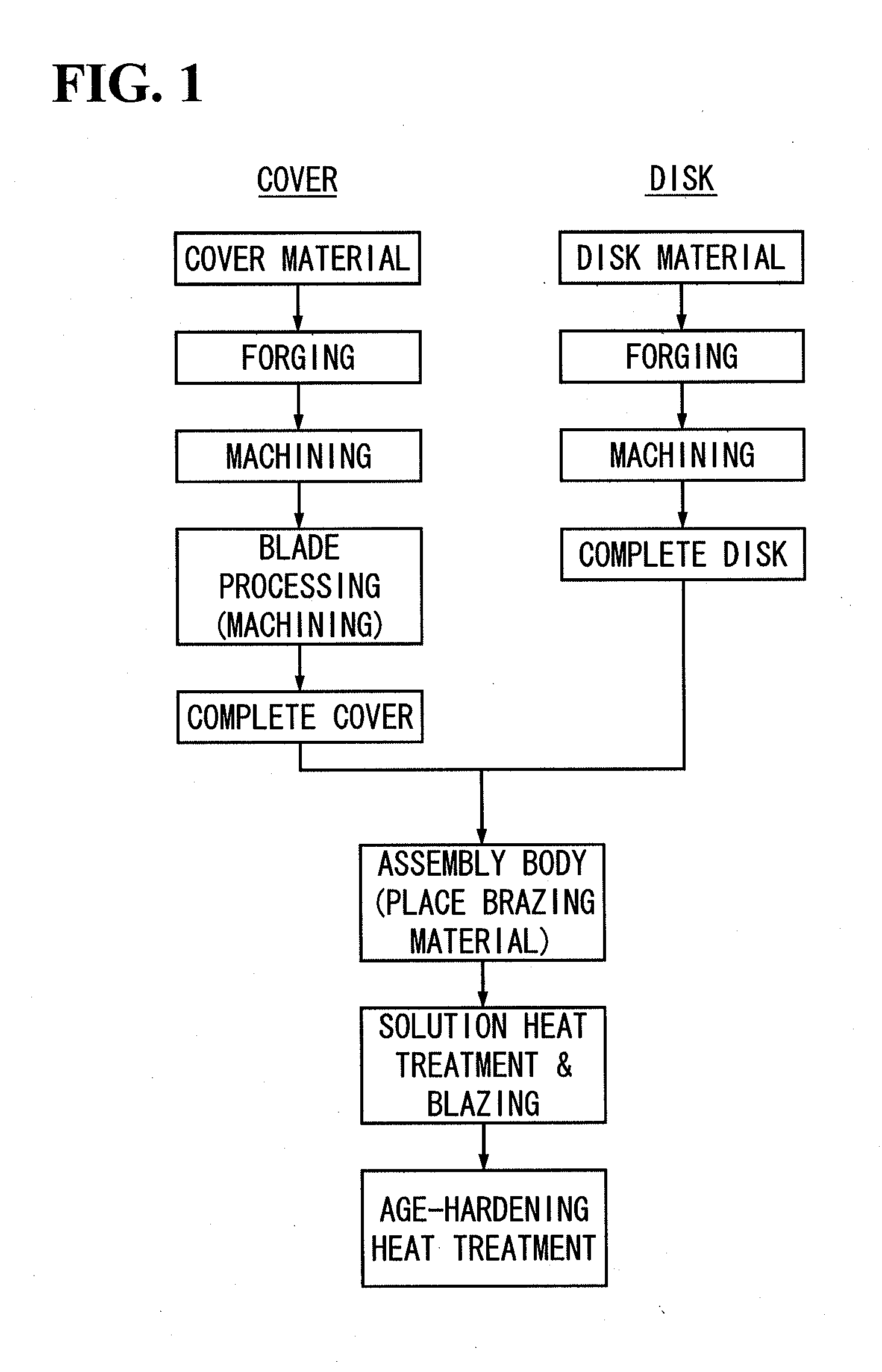
[0041]Raw materials for the disk 11 and the cover 12 are each prepared. This raw material is provided as a rod-shaped steel material. This raw material basically has the following chemical composition (mass %) stipulated in SUS630. SUS630 stipulates a stainless steel of a precipitation hardening type in which Cu is solved in a base by a solution heat treatment and a fine Cu—Ni intermetallic compound is then precipitated by an age-hardening heat treatment to improve the strength of the steel. Note that an element other than the following elements that is capable of improving the characteristics of SUS630 may be included.

[0042]Cr: 15.5% to 17.5% (preferably 15.5% to 17.0%)

[0043]Ni: 3.0% to 5.0% (preferably 3.5% to 4.5%)

[0044]Cu: 3.0% to 5.0% (preferably 3.0% to 4.0%)

[0045]Nb+Ta: 0.15% to 0.40% (preferably 0.3% to 0.40%)

[0046]C: 0.07% or lower

[0047]Si: 1.0% or lower

[0048]Mn: 1.0% or lower

[0049]P: 0.004% or lower

[0050]S: 0.03% or lower

[0051]The balance: Fe and inevita...

second embodiment

2. Second Embodiment

[0090]Next, a second embodiment is described based on the attached drawings. Members and portions identical or similar to those in the first embodiment described above are not described herein, with the use of the same reference numerals.

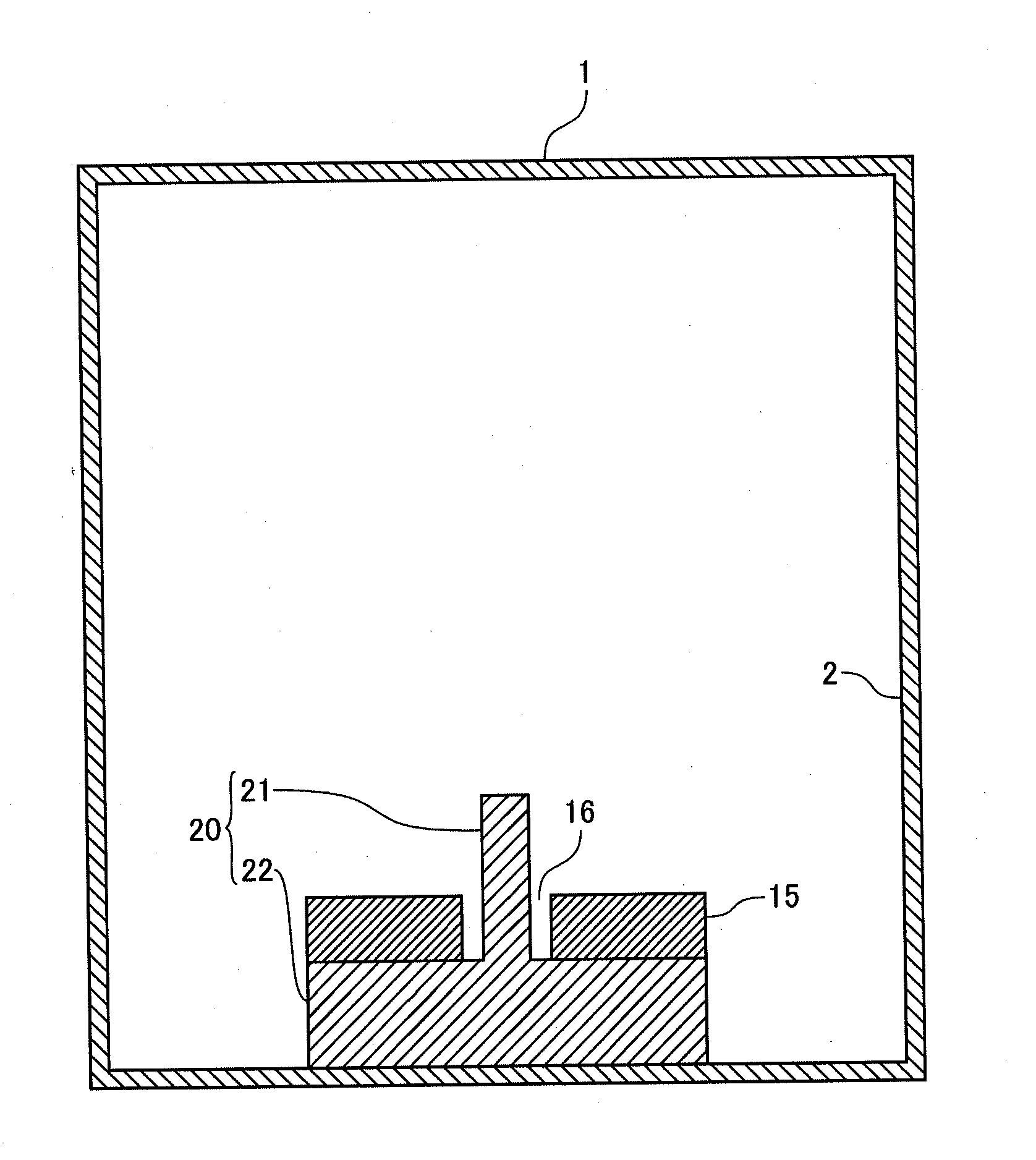
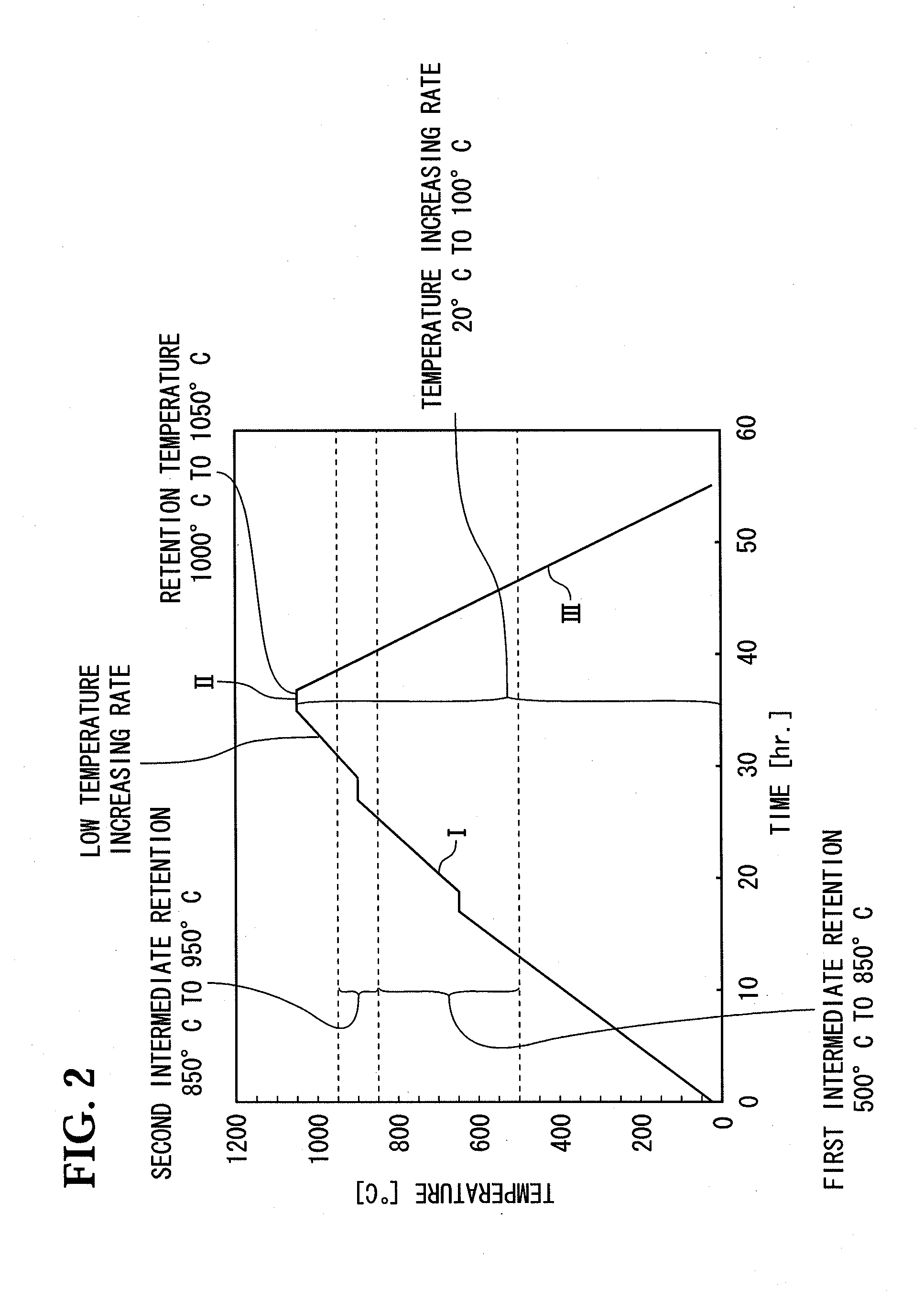
[0091]By using materials similar to those in the first embodiment, the disk 11 and the cover 12 (the blades 13) formed with a method similar to that of the first embodiment being assembled with a brazing material interposed therebetween to obtain the assembly body 15. As shown in FIG. 4, the assembly body 15 placed on a heating jig 20 is accommodated in a heating furnace 1 that performs a heat treatment. Note in the present embodiment that a shaft hole 16 of the assembly body 15 described below is identical to the shaft hole 16 of the disk 11. Also, a side closer to the shaft hole 16 of the assembly body 15 is an inner circumferential side in the assembly body 15, and a side away therefrom is an outer circumferential side.

[0092]T...


PUM

PropertyMeasurementUnit
Temperatureaaaaaaaaaa

Abstract

The present invention relates to an impeller manufacturing method in which a thermal cycle is performed on an assembly body with a brazing material formed of a Ni-containing Au alloy being placed at a bond portion of at least two impeller constituent members. The thermal cycle includes a temperature increasing process with a temperature increasing rate of 20° C. / hr. to 100° C. / hr., the process including a first intermediate retention and a second intermediate retention each keeping the temperature, the first intermediate retention performed in a temperature range of 500° C. to 850° C. and the second intermediate retention performed in a temperature range of 850° C. to 950° C. (but not including 850° C.). In the thermal cycle, the temperature is increased in a temperature range exceeding 950° C. after the second intermediate retention at a rate lower than that before the second intermediate retention.

Description

TECHNICAL FIELD[0001]The present invention relates to a method of manufacturing an impeller (a rotary wing) for use in a centrifugal compressor or another rotary machine.BACKGROUND ART[0002]For example, as shown in FIG. 7A and FIG. 7B, an impeller 10a of a centrifugal compressor is fixed to a rotational main shaft of a centrifugal compressor not shown via a shaft hole 16 provided on an inner circumferential side, and is configured to include a disk 11 with one surface curved to be thinner to the tip, a cover 12 in a shape of facing the curved surface of the disk 11, and many blades 13 provided so as to section a space between the curved surfaces of the disk 11 and the cover 12 into a vortex shape.[0003]Types of this impeller 10 include one called a three-piece type in which the disk 11, the cover 12, and the blades 13 are independently produced and mutually bonded for assembly and one called a two-piece type in which the cover 12 and the blades 13 (or the disk 11 and the blades 13) ...

Claims


Application Information

Patent Timeline
IPC IPC(8): B23K1/00
CPCB23K1/0008B23K1/0018B23K1/008B23K35/3013B23K35/3066B23P15/006B23K2101/001C21D1/785C21D9/0068C22C5/02C22C38/002C22C38/02C22C38/04C22C38/42C22C38/48F04D29/023F04D29/284F05D2230/237F05D2230/40
Inventor YOKOO, KAZUTOSHITANAKA, DAISUKEKAWADA, DAISUKENIHARA, KOSHIROTAGAGI, HIROKIWATANABE, YUJIRONAKAJIMA, HIROSHI
Owner MITSUBISHI HEAVY INDUSTIES COMPRESSOR CORP
Why Eureka
Try Eureka