Motor control device

a motor control and control device technology, applied in the direction of motor/generator/converter stopper, dynamo-electric converter control, dynamo-electric gear control, etc., can solve the problem of affecting the accuracy of axial position estimation, parameter error not only fluctuating, parameter error also increasing, etc. problem, to achieve the effect of improving the stability of sensorless control, avoiding error, and avoiding error

Active Publication Date: 2013-12-05
SANDEN CORP
View PDF9 Cites 10 Cited by
  • Summary
  • Abstract
  • Description
  • Claims
  • Application Information

AI Technical Summary

Benefits of technology

[0021]According to the motor control device as set forth in claim 1, the rotor position detecting means includes the motor parameter correcting means for correcting the parameter in order to eliminate an induced voltage difference between the detected induced voltage peak value and the detected estimated induced voltage peak value and detects the rotor position on the basis of the corrected parameter. Consequently, it is possible to eliminate an error between a theoretical value and an actual value of the motor parameter and avoid a sensorless uncontrollable state involved in occurrence of the error. Therefore, it is possible to improve stability of the sensorless control for the permanent magnetic synchronous motor.
[0022]According to the invention as set forth in claims 2 and 3, more specifically, the parameter to be corrected is winding resistance of the coil and a magnetic flux amount of the permanent magnet. These parameters tend to be affected by a temperature change to which the motor is exposed and an error of the parameters also tends to be large. Therefore, it is possible to effectively improve stability of the sensorless control through elimination of the error.
[0023]According to the invention as set forth in claim 4, the motor parameter correcting means corrects the parameter according to an operation state of the motor. Therefore, it is possible to change a correction amount of the parameter that changes according to the operation state of the motor. Consequently, it is possible to further improve accuracy of the sensorless control and further improve stability of the sensorless control.
[0024]According to the invention as set forth in claim 5, more specifically, the motor parameter correcting means corrects the parameter on the basis of the current phase detected by the rotor position detecting means and the number of revolutions detected by the revolution number detecting means as an operation state of the motor.
[0025]According to the invention as set forth in claim 6, the motor parameter correcting means changes an operation state of the motor to determine a correction amount of the parameter. Therefore, it is possible to spontaneously perform the correction of the motor parameter. Consequently, it is possible to further improve accuracy of the sensorless control and further improve stability of the sensorless control.
[0026]According to the invention as set forth in claim 7, the motor control device includes abnormality detecting means for determining that the motor is abnormal and detecting the abnormality when the induced voltage difference deviates exceeding a predetermined range even when the parameter is corrected by the motor parameter correcting means. Therefore, it is possible to quickly detect, as an abnormality of the motor, inability to eliminate the induced voltage difference even with the motor parameter correcting means, stop an output of the motor, and improve reliability of the sensorless control of the motor.

Problems solved by technology

However, it is known that, since the imaginary axis is only an axis assumed in the controller, an angle error of Δθ is present between actual d and q axes and, in order to efficiently stably operate the motor, it is necessary to quickly and accurately converge this Δθ to zero.
Therefore, an error between a theoretical value and an actual value of the parameter greatly affects axial position estimation accuracy.
Such an error of the parameter not only occurs from the individual difference of the motor but also fluctuates according to an environment to which the motor is exposed.
In particular, since the coil is formed of a copper wire in general, actual winding resistance of the coil tends to fluctuate according to a temperature to which the motor is exposed and the parameter error also increases.

Method used


Image

  • Motor control device
  • Motor control device
  • Motor control device

Examples


first embodiment

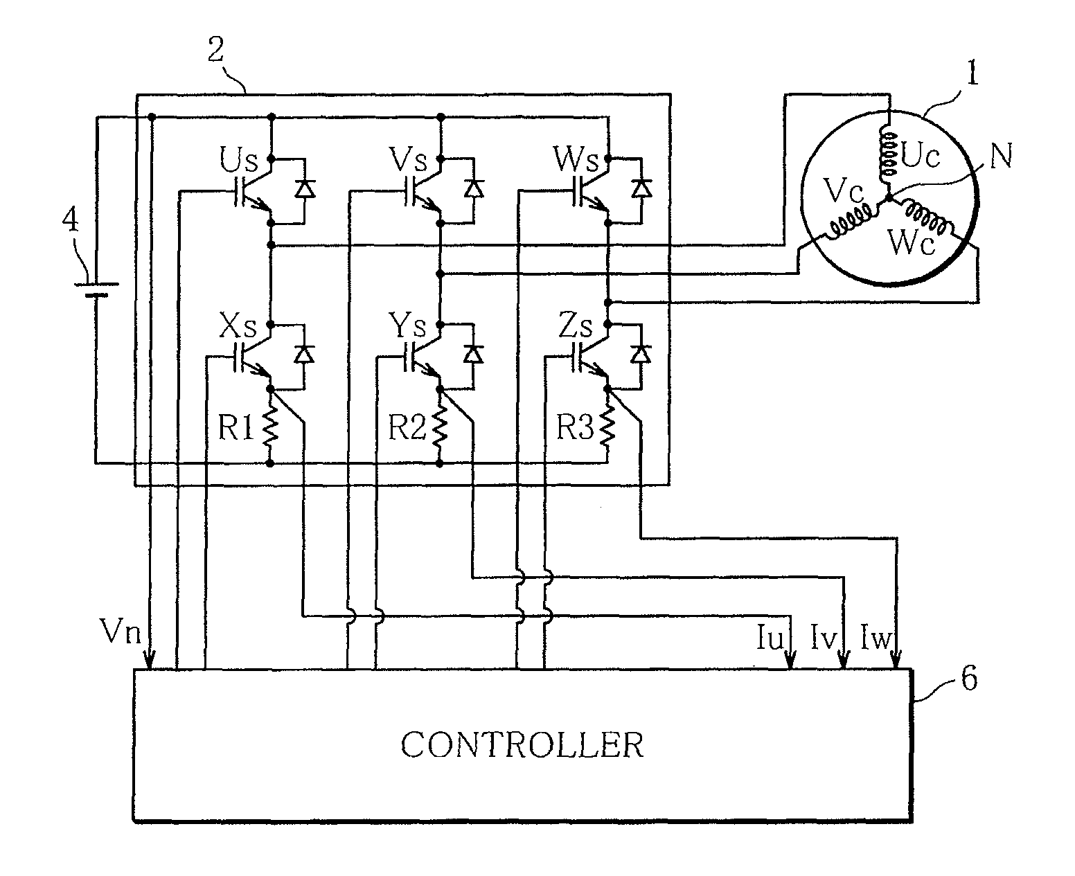
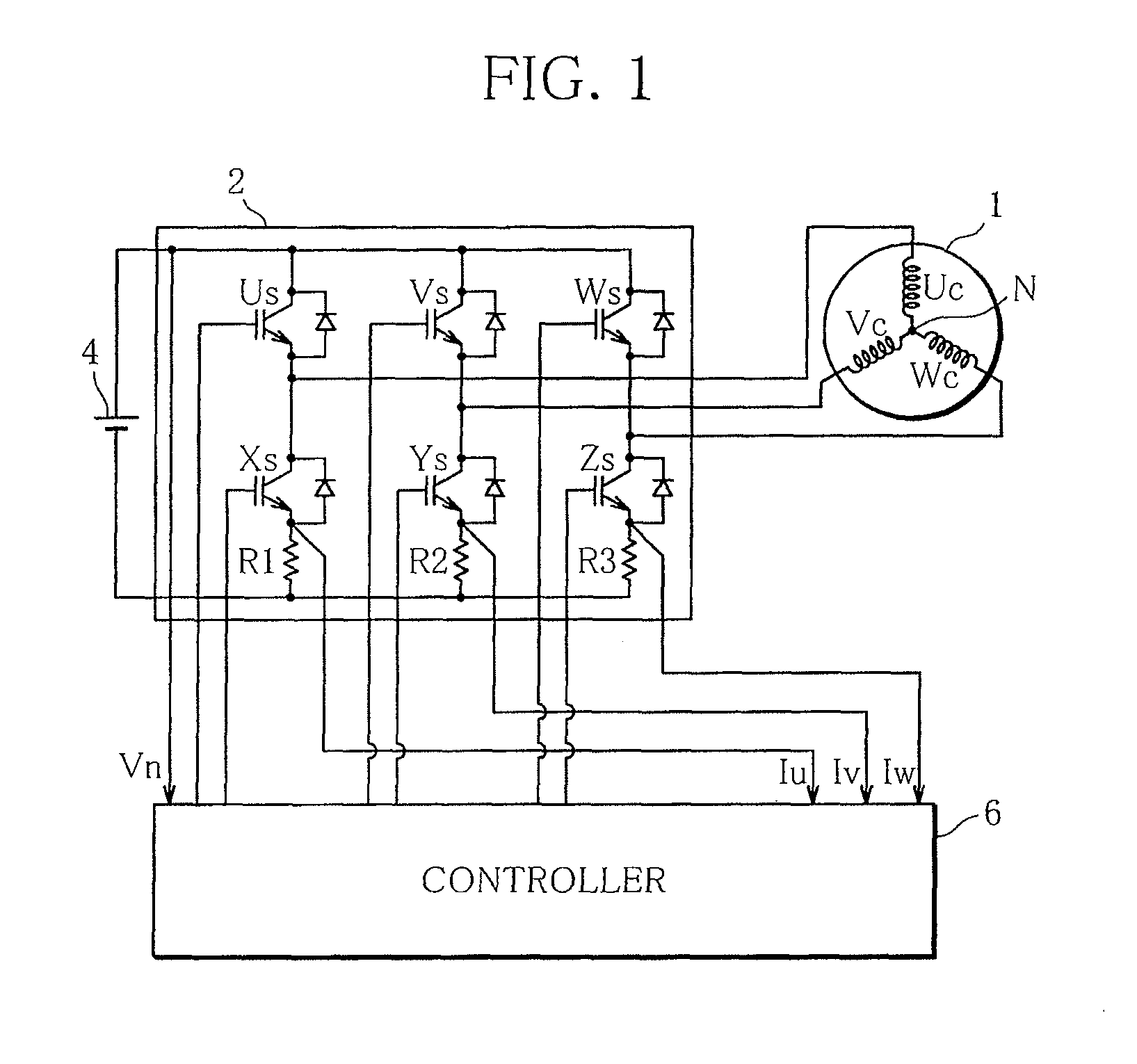
[0040]FIG. 1 is a configuration diagram of a motor control device according to the present invention. The motor control device is configured from a motor 1, an inverter 2, a direct-current power supply 4, and a controller 6 incorporating a microcomputer.

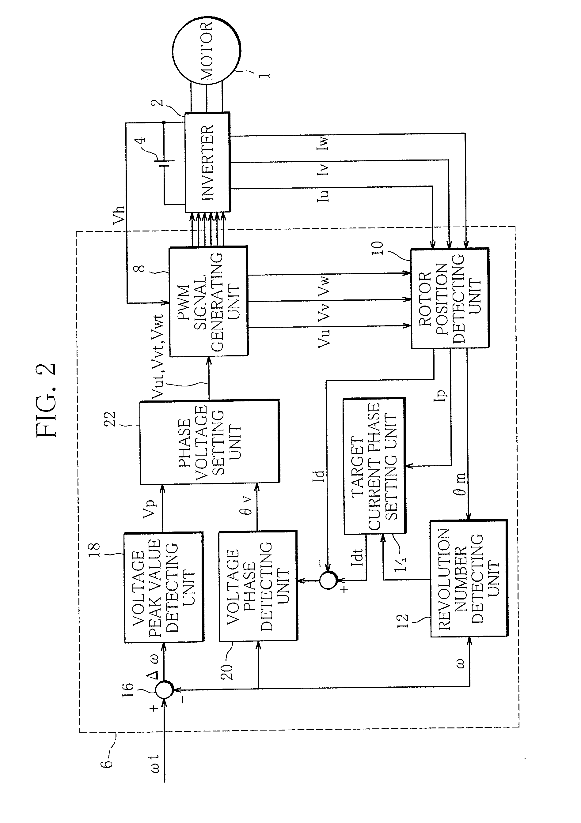
[0041]FIG. 2 is a control block diagram showing sensorless control of the motor 1 performed by the controller 6. The controller 6 includes a PWM signal generating unit 8, a rotor position detecting unit (rotor position detecting means) 10, a revolution number detecting unit (revolution number detecting means) 12, a target current phase setting unit (current phase setting means) 14, an adder 16, a voltage peak value detecting unit 18, a voltage phase detecting unit 20, and a phase voltage setting unit (phase voltage setting means) 22.

[0042]The motor 1 is a three-phase blushless DC motor. The motor 1 includes a not-shown stator including coils of three phases (a U-phase coil Uc, a V-phase coil Vc, and a W-phase coil Wc) and a not-shown...

second embodiment

[0076]Next, the present invention is explained.

[0077]FIG. 7 is a control block diagram showing the rotor position detecting unit 10 according to this embodiment in detail. Note that, for example, a basic configuration of a motor control device and a basic control method for the motor 1 such as sensorless control are the same as those in the case of the first embodiment. Therefore, explanation thereof is omitted.

[0078]As in the case of the first embodiment, the motor parameter correcting unit 30 in this embodiment detects, using the motor parameters (ψ, Ld, Lq, R, and ω), which are machine constants peculiar to the motor, the estimated induced voltage peak value Ep′ from the motor vector chart shown in FIG. 6 and the data table generated on the premise that Expressions 2 and 3 hold. The motor parameter correcting unit 30 calculates a correction amount Δψ of a permanent magnet magnetic flux amount ψ according to the following expressions using the induced voltage peak value Ep, which ...

third embodiment

[0097]Next, the present invention is explained.

[0098]In this embodiment, a method of weighting and correcting the magnetic flux amount ψ and the winding resistance R according to an operation state of a motor is adopted.

[0099]More specifically, when the motor is operated at low speed and high torque, since a relational expression ωψRI holds, the influence of an error of the magnetic flux amount ψ is large. Therefore, correction of the magnetic flux amount ψ is prioritized by correcting the induced voltage E.

[0100]More specifically, a map in which an operation area A1 for correcting only the magnetic flux amount ψ and an operation area A2 for correcting only the induced voltage E are divided and provided on a coordinate of the electric current I with respect to the number of revolutions ω of the motor 1 shown in FIG. 11 is prepared in the motor parameter correcting unit 30 in advance. A correction target is selected by determining in which of the areas A1 and A2 an operation state of...


PUM


Abstract

It is an object of the present invention to provide a motor control device that can improve stability of sensorless control of a permanent magnetic synchronous motor. Rotor position detecting means (10) includes motor parameter correcting means (30) for correcting a parameter (winding resistance of a coil, a magnetic flux amount of a permanent magnet), which is a machine constant of a motor, in order to eliminate an induced voltage difference between a detected induced voltage peak value and a detected estimated induced voltage peak value and detects the rotor position on the basis of the corrected parameter.

Description

TECHNICAL FIELD[0001]The present invention relates to a motor control device, and more particularly, to a motor control device that variably controls the speed of a permanent magnetic synchronous motor through sensorless control.BACKGROUND ART[0002]As a motor having high efficiency and a wide variable speed range, a permanent magnetic synchronous motor (PMSM), in particular, an interior permanent magnetic synchronous motor (IPMSM) in which a permanent magnet is embedded in a rotor has found extensive applications such as a compressor driving motor of an air conditioner for vehicle and a drive motor for electric automobile. Demand for the motor is expected.[0003]A motor control device that controls driving of the motor of this type is composed of a motor, an inverter, a direct-current power supply, and a controller incorporating a microcomputer.[0004]In the operation of the motor, in general, the controller detects an electric current flowing through a coil wound around a stator (arm...

Claims


Application Information

Patent Timeline
Patent Type & Authority Applications(United States)
IPC IPC(8): H02P6/18H02P21/00H02P27/04H02P21/18H02P21/24H02P21/28
CPCH02P6/182H02P21/26H02P21/18
Inventor HIRONO, DAISUKE
Owner SANDEN CORP
Why Eureka
Try Eureka