2D Dipole Localization Using Absolute Value of MCG Measurements

Active Publication Date: 2013-12-05
SEIKO EPSON CORP
View PDF1 Cites 27 Cited by
  • Summary
  • Abstract
  • Description
  • Claims
  • Application Information

AI Technical Summary

Benefits of technology

[0025]The above objects are met in a system/method capable of solving the inverse problem and of generating magnetic images from magnitude images of a magnetic field, or flux. In es

Problems solved by technology

Simulating MCG medical equipment in a laboratory can be difficult and expensive.
Most laboratory magnetic field detection equipment, such as the Fluxgate sensor MAG639™, are ca

Method used


Image

  • 2D Dipole Localization Using Absolute Value of MCG Measurements
  • 2D Dipole Localization Using Absolute Value of MCG Measurements
  • 2D Dipole Localization Using Absolute Value of MCG Measurements

Examples


Embodiment Construction

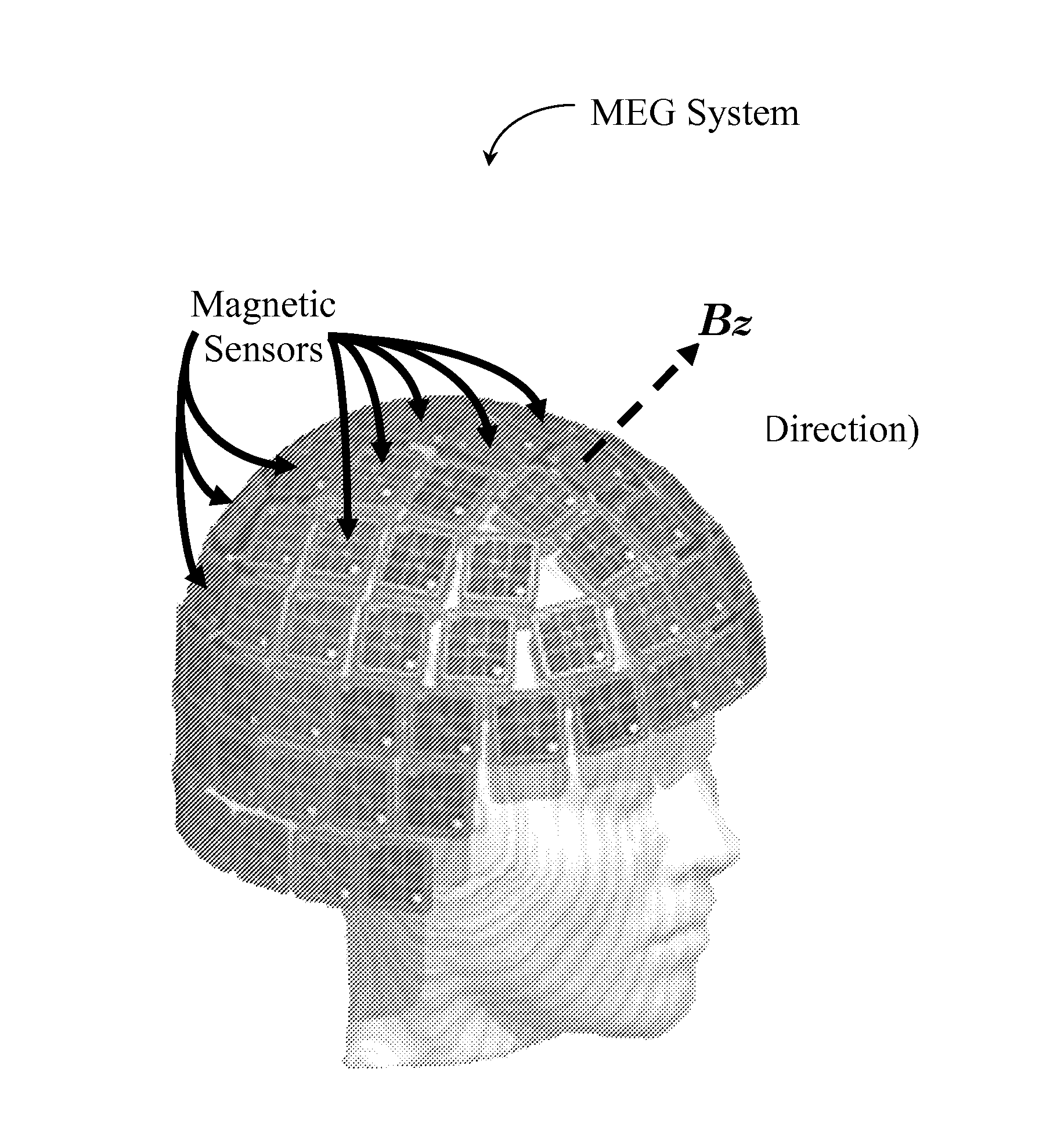
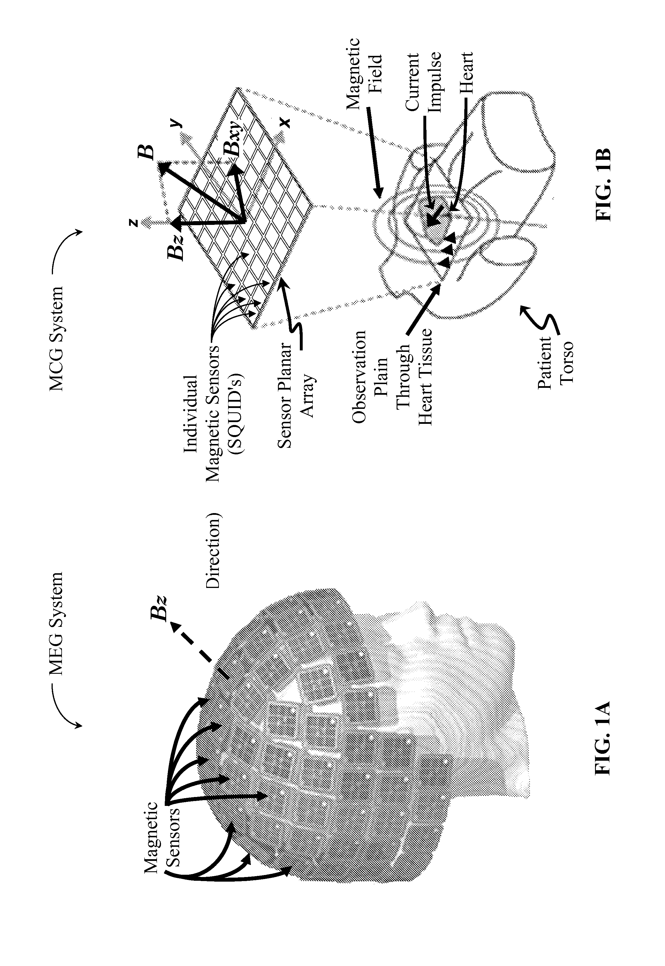
[0071]An MCG system require highly sensitive magnetic sensors to produce images of magnetic fields emanating from living tissue, such as human heart tissue. Due to the high sensitivity requirements of an MCG system, its magnetic sensors are typically comprised of superconducting quantum interference devices (SQUIDs).

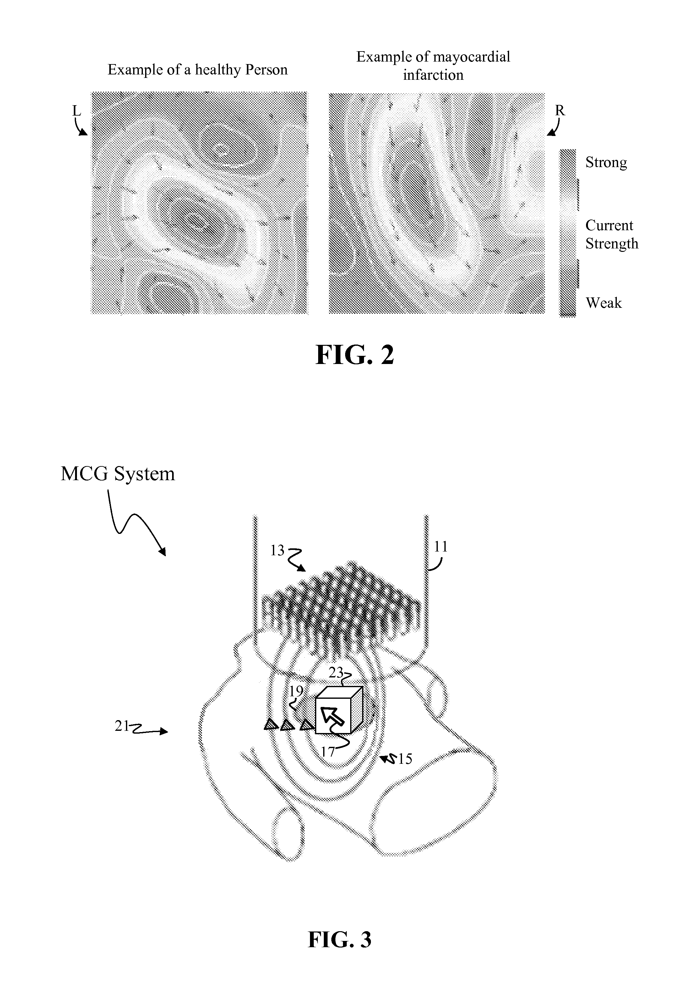
[0072]With reference to FIG. 3, a typical MCG system consists of an MCG sensor unit 11 housing a small number of individual SQUID sensors 13 (typically arranged as a planar array of sixty-four or fewer sensors). Electric impulses 17 within the body create a magnetic field 15. In the present case, the human heart 19 functions as the observed source of electric impulses 17 (i.e. as the current source).

[0073]Each SQUID sensor 13 is a capture point, and hereinafter may be referred to as a capture 13. Each capture 13 measures a one-dimensional (i.e. 1D) magnetic waveform in a direction perpendicular to the sensor planar array (i.e. the z-direction) emanating from the patient'...


PUM


Abstract

A magnetic imaging systems produces magnetic magnitude images using magnetic sensors capable of determining only the absolute value of a detected magnetic field and provide no information regarding the positive or negative sign of the detected magnetic image. A 2D dipole location is determines the 2D location of a dipole within a magnetic magnitude image by finding the minimum of the derivative of the absolute value of the magnetic field. This 2D dipole location is then used to determine the 3D position and momentum of a current dipole responsible for the observed magnetic magnitude image. The current dipole is used to generate a magnetic image that incorporate positive and negative sign information.

Description

BACKGROUND[0001]1. Field of Invention[0002]The present invention relates to the field of magnetic imaging. More specifically, it relates to the generating of high quality magnetic imaging using lower quality laboratory equipment that is limited to only measuring the absolute value of an observed magnetic field.[0003]2. Description of Related Art[0004]Electric current source estimation is a common problem in various areas of electromagnetic imaging technology. One area of particular interest is the imaging of electric fields emanating from living tissue. Living organisms generate electric impulses, which result in electric fields, and electric imaging (or electric field imaging) makes it possible to capture images of these electric fields (hereinafter termed electric images). Electric imaging has found wide application in the medical field, where it is often desirable to reconstruct an electric impulse, or dipole, from its electric image.[0005]As it is known in the art, an electric c...

Claims


Application Information

Patent Timeline
IPC IPC(8): A61B5/05
CPCA61B5/242A61B5/243A61B5/245
Inventor WU, CHENYUXIAO, JING
Owner SEIKO EPSON CORP
Why Eureka
Try Eureka