Combustion exhaust gas treatment system and method of treating combustion exhaust gas

a technology of exhaust gas treatment system and combustion exhaust gas, which is applied in the direction of machines/engines, separation processes, mechanical equipment, etc., can solve the problems of low limit the arrangement of each device, and achieve high degree of freedom in plant design, high thermal efficiency, and high removal capability

Active Publication Date: 2013-12-12
MITSUBISHI POWER LTD
View PDF7 Cites 14 Cited by
  • Summary
  • Abstract
  • Description
  • Claims
  • Application Information

AI Technical Summary

Benefits of technology

[0020]The combustion exhaust gas treatment system or the method of treating combustion exhaust gas according to the present invention has a high degree of freedom in plant design as well as high thermal efficiency and high CO2 removal capability. In addition, according to the present invention, the consumption of Steam 62 extracted from a turbine system can be reduced, and decrease in power generation efficiency can be suppressed by heating CO2 absorbent with sensible heat recovered from exhaust gas in Gas Cooler 4 through heat medium in Heater 38a or 38b provided in a CO2 absorbent line at an inlet or outlet of Desorption Column 40 and increasing calorific value to be supplied to Desorption Column 40.

Problems solved by technology

Nonetheless, there is limitation in arrangement of each device because a plurality of heat exchangers need to be provided in the middle of the line transporting absorbent from the CO2 absorption column to the desorption column.
Therefore, the degree of freedom in plant design is low.

Method used


Image

  • Combustion exhaust gas treatment system and method of treating combustion exhaust gas
  • Combustion exhaust gas treatment system and method of treating combustion exhaust gas
  • Combustion exhaust gas treatment system and method of treating combustion exhaust gas

Examples


embodiment 1

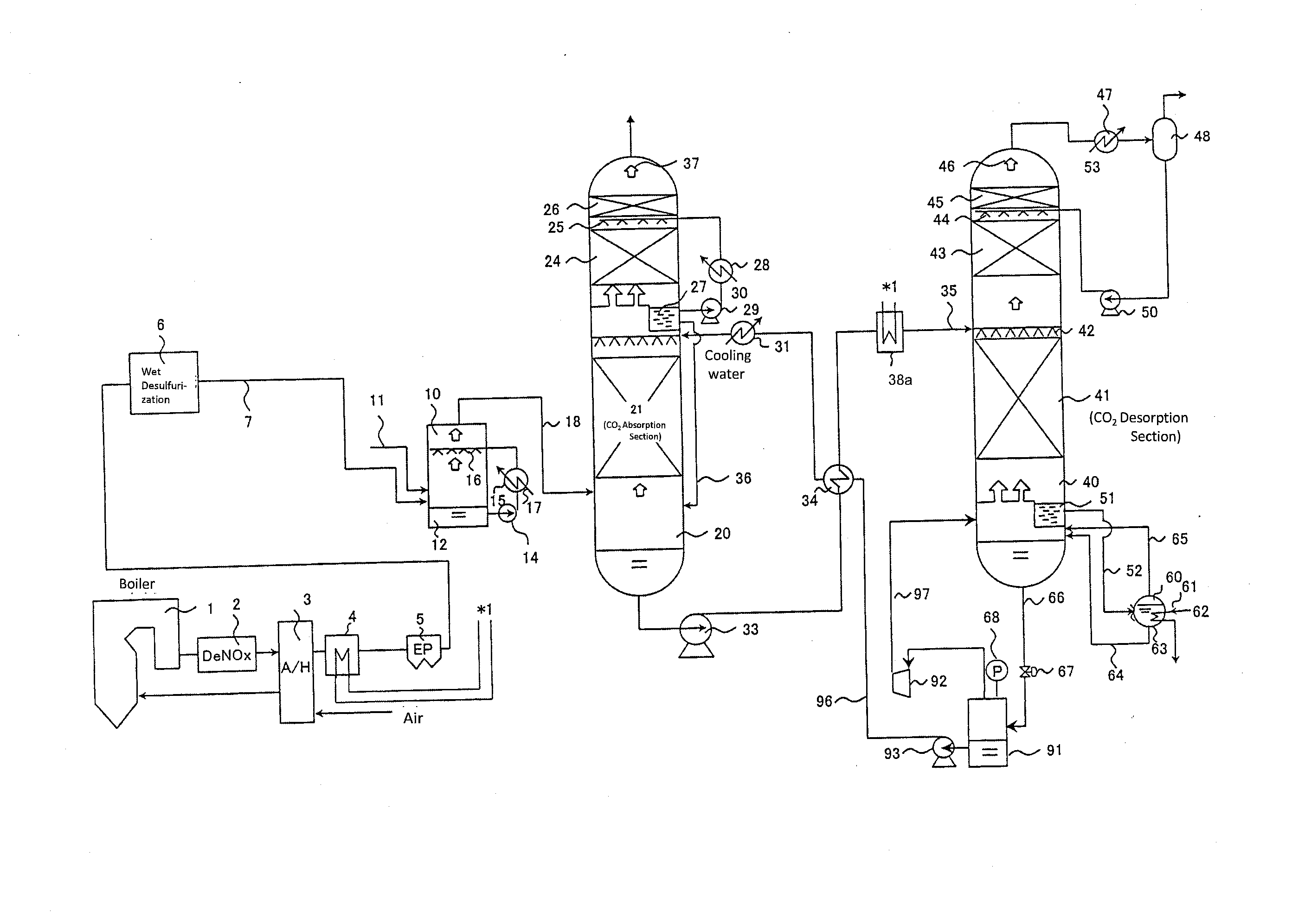
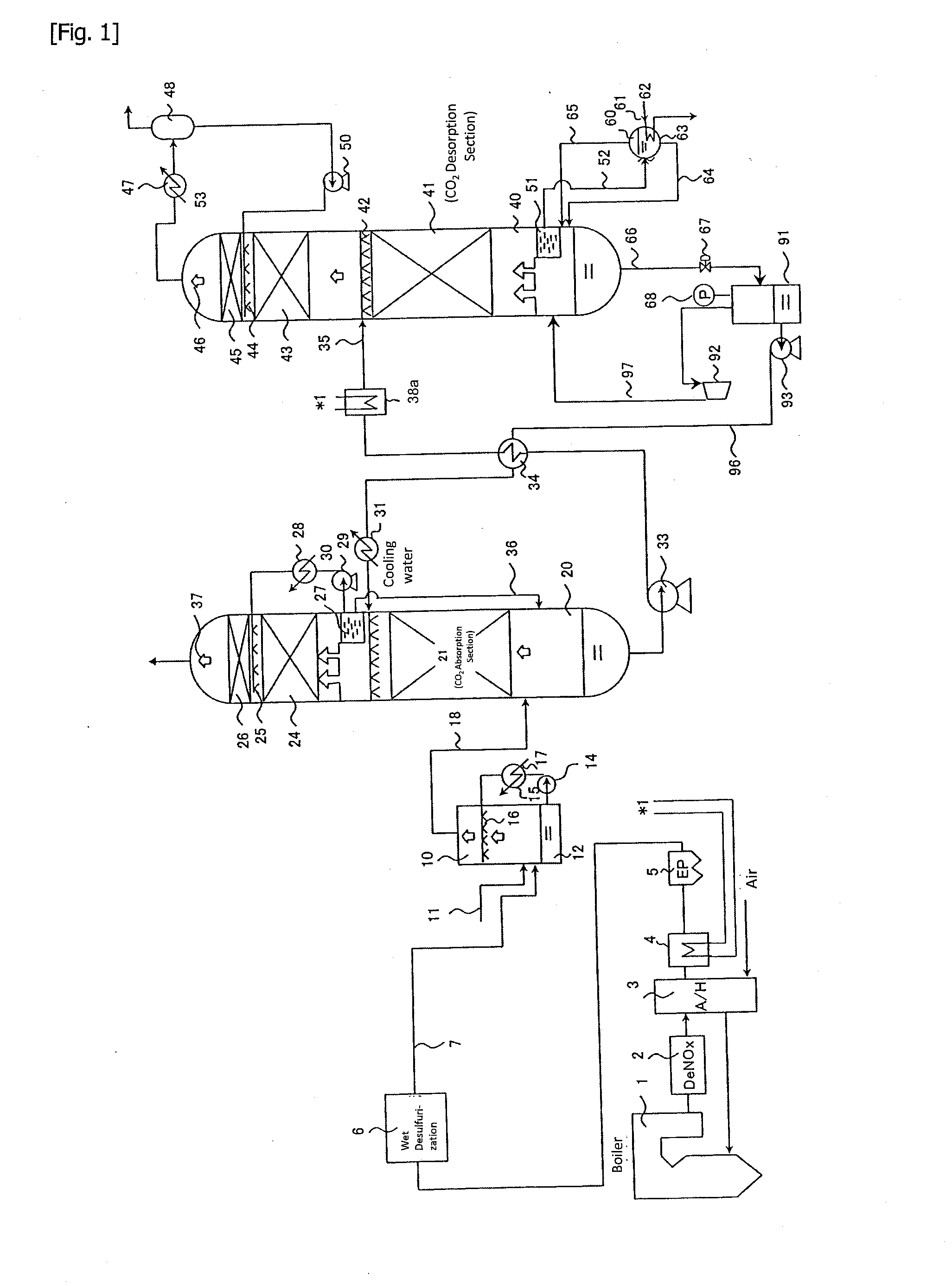
[0026]FIG. 1 shows a combustion exhaust gas treatment system of Embodiment 1 according to the present invention. This combustion exhaust gas treatment system is, for example, a part of a power generation plant. This combustion exhaust gas treatment system comprises Boiler (Combustion Apparatus) 1, Denitration Device 2, Air Heater 3, Gas Cooler (Heat Exchanger (A)) 4, Electrostatic Precipitator 5, Wet Desulfurization Device 6, Pre-scrubber 10, CO2 Absorption Column 20, Desorption Column 40, Reboiler 60, Flash Tank 91 and the like.

[0027]Combustion exhaust gas of fossil fuels such as coal and the like discharged from Boiler 1 is passed through Denitration Device 2 to remove nitrogen oxides, and then heat exchanged with air in Air Heater 3 to cool down to, for example, 130 to 220° C. The air heated in Air Heater 3 is supplied to Boiler 1. The exhaust gas passed through Air Heater 3 is cooled in Gas Cooler 4, for example, down to about 85 to 100° C. Heat contained in the exhaust gas is r...

embodiment 2

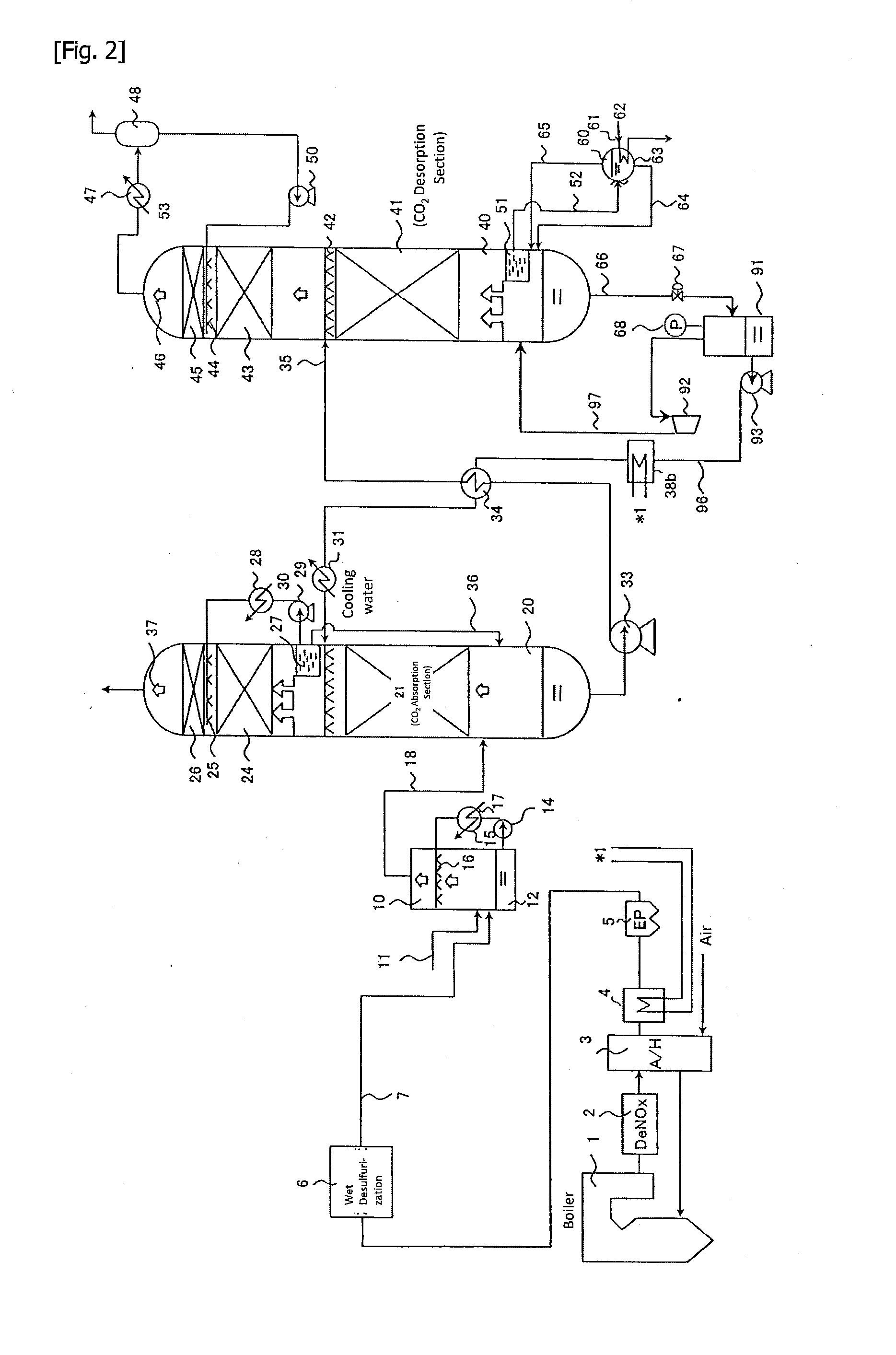
[0034]FIG. 2 shows a combustion exhaust gas treatment system of Embodiment 2 according to the present invention.

[0035]In the system shown in FIG. 2, Heater (Heat exchanger (C)) 38b is provided at Outlet Line 96 of Flash Tank 91. The heat source of Heater 38b is heat medium which has recovered heat in Gas Cooler 4. Regenerated CO2 absorbent is heated in Heater 38b to a temperature (for example, 130° C. or higher) at which absorbent flowing into the desorption column can be heated by heat exchange in Heat Exchanger 34. Then the absorbent flowing into the desorption column can be easily brought to a predetermined temperature (for example, 95 to 105° C.) in Heat Exchanger 34. As a result, the consumption of Steam 62 extracted from a turbine system can be reduced, and decrease in power generation efficiency can be suppressed.

embodiment 3

[0036]FIG. 3 shows a combustion exhaust gas treatment system of Embodiment 3 according to the present invention.

[0037]In the system shown in FIG. 3, Gas Reheater (Heat Exchanger (D)) 8 is provided at CO2 Absorption Column 20. Heater (Heat Exchanger (B)) 38a is also provided as in the system shown in FIG. 1. The heat source of Heater 38a and Gas Reheater 8 is heat medium which has recovered heat in Gas Cooler 4. CO2 absorbed absorbent is heated to a predetermined temperature (for example, 95 to 105° C.) by Heater 38a. By this, the consumption of Steam 62 extracted from a turbine system can be reduced, and decrease in power generation efficiency can be suppressed. Further, sensible heat recovered in Gas Cooler 4 can be used for reheating CO2 Removed Gas 37 through heat medium by Gas Reheater 8 provided at the top of Absorption Column 20.

Explanation of Symbols

[0038]1: Boiler;

[0039]2: Denitration Device;

[0040]3: Air Heater;

[0041]4: Gas Cooler (Heat Exchanger (A));

[0042]5: Dry Electrost...


PUM

PropertyMeasurementUnit
pressureaaaaaaaaaa
pressureaaaaaaaaaa
temperatureaaaaaaaaaa

Abstract

A combustion exhaust gas treatment system comprising: a heat exchanger (A) for recovering heat contained in the combustion exhaust gas into heat medium, an absorption column for obtaining CO2 removed gas by absorbing CO2 in the combustion exhaust gas into absorbent, a heat exchanger (B) for applying heat recovered by heat medium to the CO2 absorbed absorbent, a desorption column for desorbing the absorbent by removing CO2 from the CO2 absorbed absorbent, a flash tank for flash vaporizing the desorbed absorbent and a heat exchanger (E) for transferring heat from the desorbed absorbent to the CO2 absorbed absorbent, wherein the CO2 absorbed absorbent can be supplied from the absorption column to the desorption column via the heat exchanger (E) and the heat exchanger (B) in this order, and the desorbed absorbent can be supplied from the desorption column to the absorption column via the flash tank and the heat exchanger (E) in this order.

Description

TECHNICAL FILED[0001]The present invention relates to a combustion exhaust gas treatment system and a method of treating combustion exhaust gas to absorb and separate carbon dioxide (CO2) in combustion exhaust gas of fossil fuel and the like. More specifically, the present invention relates to a combustion exhaust gas treatment system and a method of treating combustion exhaust gas having a high degree of freedom in plant design as well as high thermal efficiency and high CO2 removal capability.BACKGROUND ART[0002]In thermal power generation facilities and boiler equipment, a large amount of fuels such as coal and heavy oil are burned, generating a large amount of carbon dioxide. In recent years, it has been proposed that discharge of carbon dioxide (CO2) should be globally controlled in view of air pollution and global warming. As one of the techniques for separation and recovery of CO2, known is a method of absorbing CO2 into absorbent such as an amine compound, i.e., a chemical a...

Claims


Application Information

Patent Timeline
Patent Type & Authority Applications(United States)
IPC IPC(8): F01N3/08C01B32/50
CPCF01N3/08B01D53/62B01D53/1475B01D2257/504B01D53/343B01D2258/0283B01D2252/20478B01D2257/30B01D2257/404B01D2259/65C01B32/50Y02P20/10Y02P20/151Y02P20/50Y02C20/40
Inventor SHIMAMURA, JUNKATSUBE, TOSHIOYOKOYAMA, KOUICHIKIDERA, YOSHIHIROMISHIMA, NOBUYOSHIORITA, HISAYUKI
Owner MITSUBISHI POWER LTD
Why Eureka
Try Eureka