Digester gas mixer for liquid waste treatment

a gas mixer and liquid waste technology, applied in biological water/sewage treatment, filtration separation, separation processes, etc., can solve the problems of uneven biological decomposition of sludge, mixers are prone to mechanical failure, and all require large amounts of energy

Inactive Publication Date: 2013-12-12
DREWRY KRISTINN G +2
View PDF6 Cites 4 Cited by
  • Summary
  • Abstract
  • Description
  • Claims
  • Application Information

AI Technical Summary

Problems solved by technology

While mechanical mixers are very common, they all require fairly large amounts of energy, typically in the form of electricity supplied to electric motors to drive the mixers.
Further, such mixers are prone to mechanical failure.
Yet further, many mechanical mixers are not thoroughly effective, failing to supply adequate mixing to all regions of the sludge in the digester, resulting in uneven biological decomposition of the sludge over time.
However, bubble mixers using compressed gas containing oxygen, such as air, are not useable in digesters, because digesters rely for operation in large part on the activity of strictly anaerobic microbes, organisms which cannot function effectively in the presence of even relatively small amounts of oxygen.
The Perth and similar mixers, however, are subject to several limitations.
First, in a typical installation, the Perth lances do not extend to the very bottom of the digester.
These materials remain essentially undisturbed, with no improvement in their decomposition brought about by use of the Perth technology.
Second, and significantly as concerns the present invention, while the bubbles emitted from the bottom opening of a Perth lance may create some turbulence as they rise through the upper portion of the digester, the amount of turbulence caused by these moderately sized bubbles is not sufficient to mix the entire contents of the tank adequately.
In U.S. Pat. No. 4,824,571, inventors Ducellier et al. note the fact that general bubbles of the biogas emitted in anaerobic sludge decomposition in a tank produce insufficient turbulence to mix the entire contents of the tank adequately.
While the biogas from the tank emitted in moderately sized bubbles is insufficient to mix the entire contents of the tank in one session, it is sufficient to mix the entire contents of the portion of the tank contained in one sector.

Method used


Image

  • Digester gas mixer for liquid waste treatment
  • Digester gas mixer for liquid waste treatment
  • Digester gas mixer for liquid waste treatment

Examples


Embodiment Construction

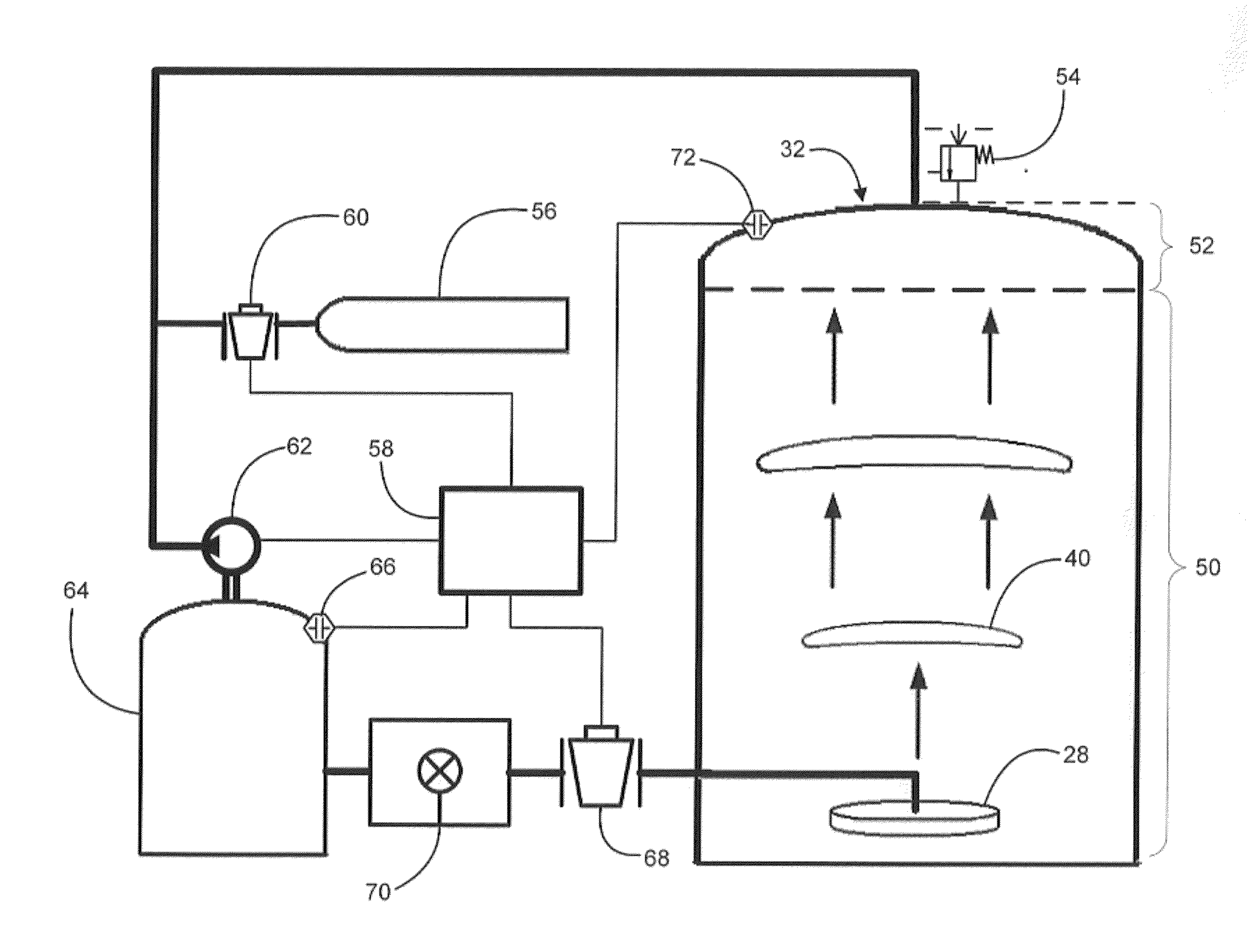
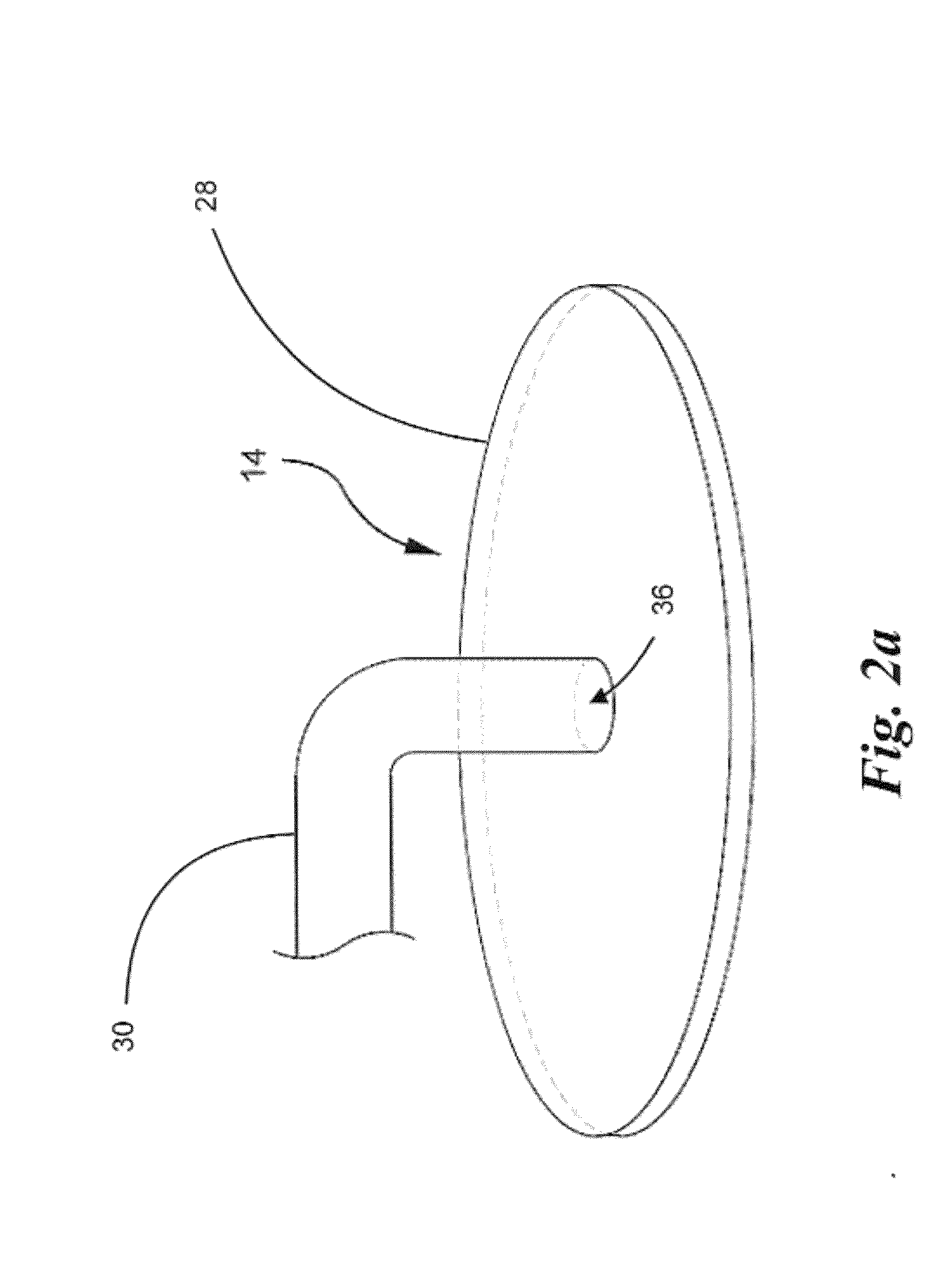
[0031]The present invention forms large mixing bubbles from biogas produced in a digester by use of gas accumulating apparatus. In some embodiments, such gas accumulating apparatus comprise bubble-forming plate assemblies that are placed in the digester in which mixing is desired. Turning to the assembly of such plates, FIG. 2a illustrates an embodiment of a bubble forming plate assembly 14 according to an embodiment of the present invention. Plate assembly 14 is immersed in sludge to be mixed. A gas distribution line 30 provides compressed gas through orifice 36 to the underside of plate 28. Plate 28 is typically made of corrosion resistant metal, or metal that has been treated for corrosion resistance, and in embodiments is on the order of eight inches in diameter. In any case, the gas, being lighter than the sludge, accumulates on the underside of plate 28 until such a large quantity has accumulated that it escapes around the edges of plate 28 to form a large bubble.

[0032]For eff...


PUM

PropertyMeasurementUnit
temperatureaaaaaaaaaa
diameteraaaaaaaaaa
diameteraaaaaaaaaa

Abstract

A mixer for anaerobic decomposition of sludge in a digester, captures and compresses biogas emitted by the decomposing sludge. The compressed biogas proceeds through supply lines to gas accumulating apparatus mounted in the lower portion of the digester, close to or on the digester floor. Biogas accumulates in the gas accumulating apparatus to emerge as large mixing bubbles from 6 inches to 10 feet in diameter along their largest dimension. The mixing bubbles are large enough to generate a strong mixing current in the sludge that moves sludge as the bubbles rise to the surface. The mixing current mixes the sludge containing dissolved and suspended pollutants to promote the conversion of the pollutants by microorganisms contained in the sludge.

Description

CROSS REFERENCE TO RELATED APPLICATION[0001]This application is a continuation-in-part of and claims priority to U.S. patent application Ser. No. 12 / 462,990 for DIGESTER GAS MIXER FOR WASTE LIQUID TREATMENT, filed Aug. 12, 2009.[0002]This application is also a continuation-in-part of and claims priority to U.S. patent application Ser. No. 13 / 830,455 for MIXING BUBBLE GENERATOR AND INSTALLATION CONFIGURATION, filed Mar. 14, 2013, which claims benefit of U.S. provisional patent application No. 61 / 741,313, filed Jul. 16, 2012.BACKGROUND OF THE INVENTION[0003]1. Field of the Invention[0004]This invention relates to mixers for mixing liquids by the injection of gas to form large mixing bubbles. More specifically, this invention relates to utilizing biogas for such mixers employed in the anaerobic decomposition of waste liquids.[0005]2. Description of the Related Art[0006]Water is frequently used to transport unwanted materials—waste—to a facility where the waste is removed or neutralized...

Claims


Application Information

Patent Timeline
Patent Type & Authority Applications(United States)
IPC IPC(8): C02F11/04
CPCC02F11/04C02F3/2893B01F2215/0431Y02E50/30Y02W10/10Y02W10/20B01F33/403B01F33/406B01F33/409
Inventor DREWRY, KRISTINN G.KOOPMANS, RICHARD J.ARNOLD, WILLIAM A.
Owner DREWRY KRISTINN G
Why Eureka
Try Eureka