This helps you quickly interpret patents by identifying the three key elements:
Problems solved by technology
Method used
Benefits of technology
Benefits of technology
Embodiments of this patent provide a lighting device that is thin, has better design flexibility, and is more efficient at dissipating heat. It also has improved control over wavelength shifting and brightness levels. Additionally, the device can enhance its brightness without adding a separate light source by using a reflection unit on a printed circuit board to improve light reflectance. Overall, this invention offers innovation for lighting design and performance.
Problems solved by technology
Unlike a florescent lamp, since the LED device does not use harmful substances such as mercury and the like, it has a low possibility to cause environmental pollution and a long life span compared to a conventional light source.
However, due to a thickness of the light guide plate itself, there is a limitation to make the thickness of an entire product thin.
Further as a material of the light guide plate is not flexible, it is disadvantageous that it would be difficult to apply the light guide plate to a part in which a bend is formed, and thus a product plan and design cannot be easily changed.
Also, as the light is partially emitted to the side of the light guide plate, light loss is generated.
Thus, it is problematic that light efficiency is reduced.
Furthermore, as a temperature of the LEDs increases at the time of light emission, it is also problematic that the LEDs' characteristics (e.g. luminous intensity and wavelength transition) are changed.
Method used
Image
Click on the blue label to locate the original text in one second.
Reading with bidirectional positioning of images and text.
Examples
second exemplary embodiment
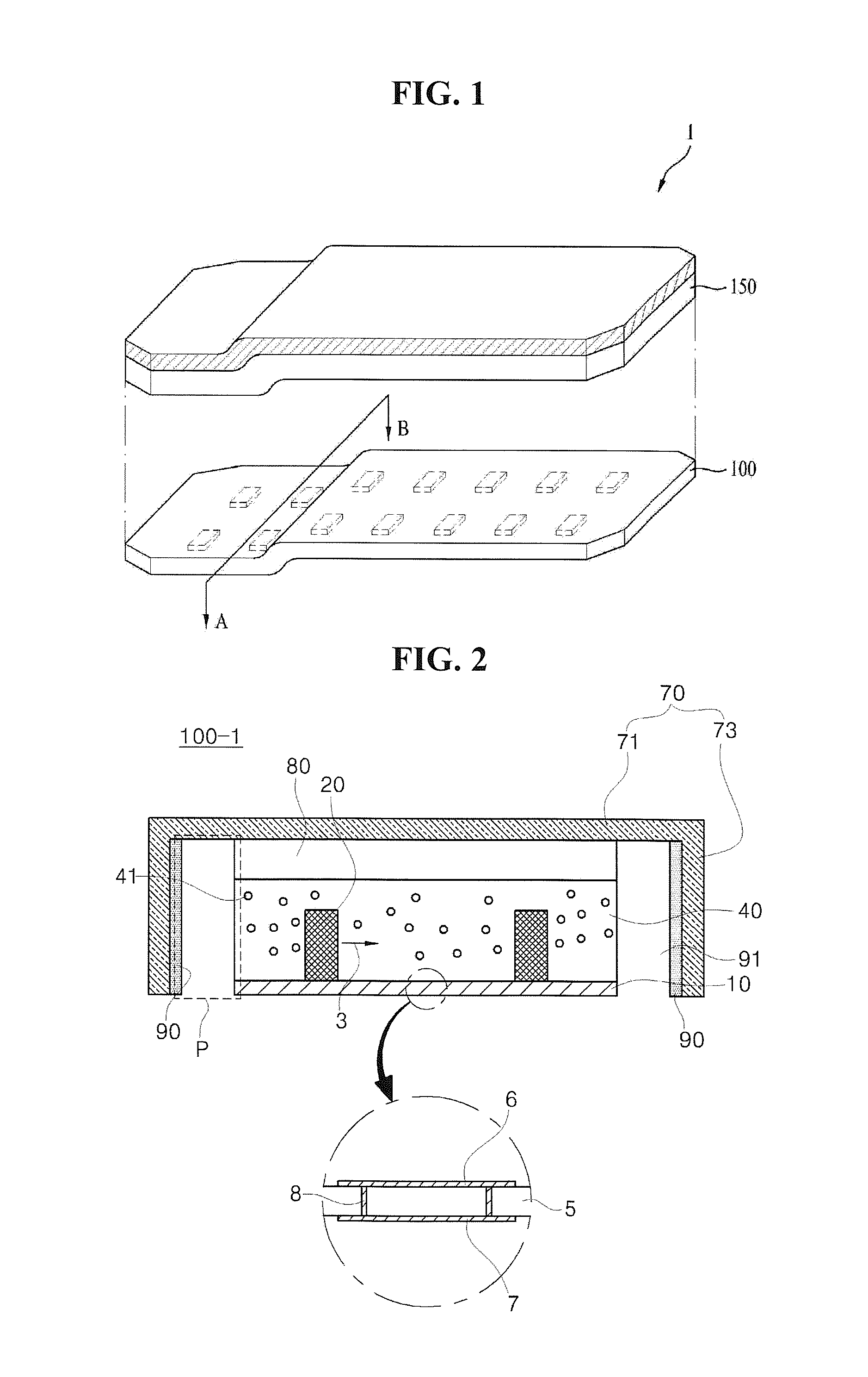
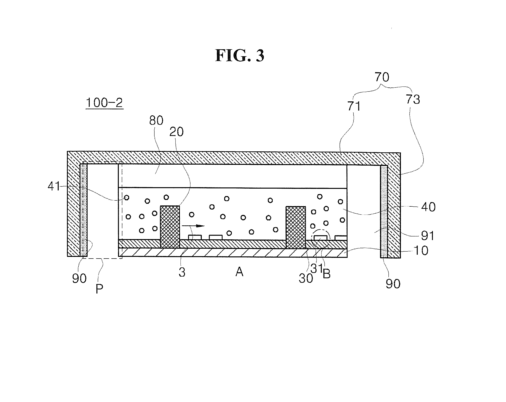
[0121]FIG. 7 illustrates a structure in which the heat dissipation member 110 is added to the light source module 100-1 of FIG. 2. However, it would also be obvious to those having ordinary skill in the art that the heat dissipation member can be also added to the light source modules 100-2, 100-3 of FIG. 3 and FIG. 6 which are the second exemplary embodiment and the third exemplary embodiment.
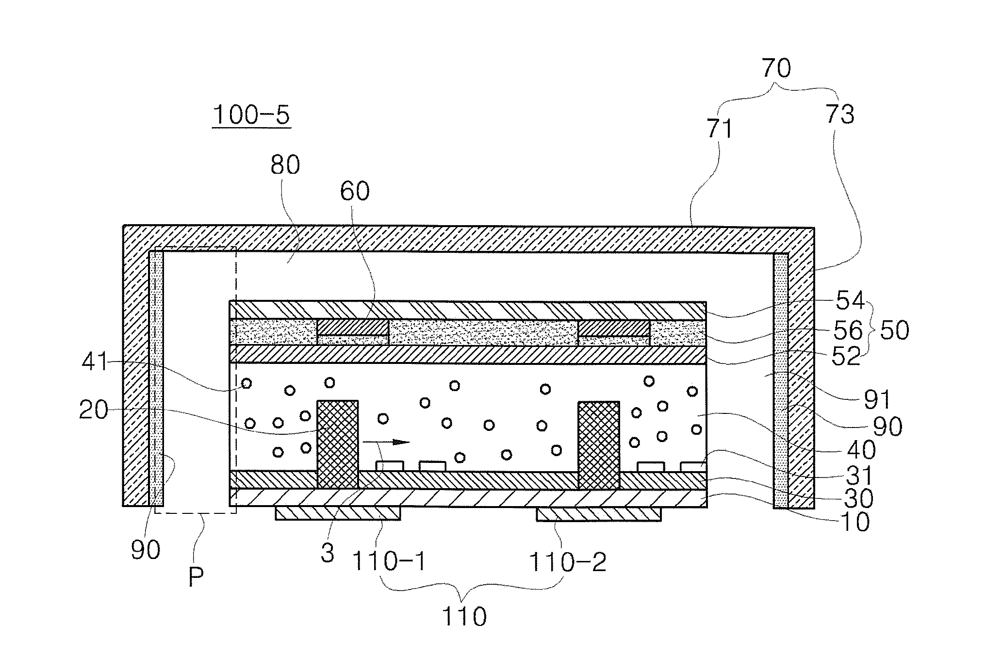
[0122]FIG. 8 shows a fifth exemplary embodiment 100-5 of the light source module illustrated in FIG. 1.
[0123]Referring to FIG. 8, the light source module 100-5, which is the optical pattern layer 50 added to the fourth exemplary embodiment 100-4, may be composed in a structure in which the optical pattern layer 50 includes a first optical sheet 52, an adhesive layer 56, an optical pattern 60 and a second optical sheet 54.
[0124]The first optical sheet 52 is disposed on the resin layer 40, and the second optical sheet is disposed on the first optical sheet 52. The first optical sheet 52 and the ...
eighth exemplary embodiment
[0147] thanks to the through part 310-1, since the heat generated from the light source 20 is directly transmitted to the heat dissipation member 310 and the transmitted light is emitted to the outside, the heat dissipation efficiency can be improved.
[0148]Also, it would be obvious to those having ordinary skill in the art that the heat dissipation member 310 can be also included in the aforesaid second and third exemplary embodiments even through this is not illustrated in the drawing.
[0149]FIG. 13 shows a ninth exemplary embodiment 100-9 of the light source module illustrated in FIG. 1, FIG. 14 shows a tenth exemplary embodiment 100-9 of the light source module illustrated in FIG. 1, and FIG. 15 shows an eleventh exemplary embodiment 100-9 of the light source module illustrated in FIG. 1.
[0150]The light source module illustrated in FIG. 13 to FIG. 15 may have a structure in which an additional element is further added to the reflection sheet 30, the second optical sheet 54 and the...
case 1
[0268 represents a measured temperature of the light emitting chip when a length of the first direction of the first portion and the second portion in the side surface part of the first lead frame is identical to that of the third portion. Case 2 represents a measured temperature of the light emitting chip illustrated in FIG. 22. Case 3 represents a measured temperature of the light emitting chip illustrated in FIG. 33.
[0269]Referring to FIG. 40, the measured temperature (t1) of case 1 is 44.54° C., the measured temperature (t2) of case 2 is 43.66° C., and the measured temperature (t3) of case 3 is 43.58° C.
[0270]Accordingly, as designs of the connection parts of the first side surface part 714 of the first lead frame 620 are changed, a heat dissipation effect of the present exemplary embodiment can be improved. Thus, since an increase in temperature of the light emitting chip 640 mounted to the light emitting device packages 200-1, 200-2 at the time of light emission may be relieve...
PUM
Abstract
Provided is a lighting device, comprising: a light source module comprising: at least one light source disposed on a printed circuit board; and a resin layer disposed on the printed circuit board so that the light source is embedded; an indirect light emission unit which is formed in at least any one of one side and another side of the light source module, and which reflects light irradiated from the light source; and a diffusion plate having an upper surface formed on the light source module, and a side wall which is integrally formed with the upper surface and which is adhered onto an outer side surface of the indirect light emission unit, wherein a first separated space is formed between the light source module and the upper surface of the diffusion plate, whereby flexibility of the product itself can be secured, and durability and reliability of the product can be also improved while indirect light emission using a flare effect can be implemented.
Description
CROSS-REFERENCE TO RELATED APPLICATION[0001]This application claims to the benefit of Korean Patent Application No. 10-2012-0062529, filed Jun. 12, 2012, and Korean Patent Application Nos. 10-2012-0065263 and 10-2012-0065261, filed Jun. 18, 2012 which are hereby incorporated by reference in their entirety.BACKGROUND OF THE INVENTION[0002]1. Field of the Invention[0003]Embodiments of the present invention relate to the technology field of a lighting device.[0004]2. Description of the Related Arts[0005]An LED (Light Emitted Diode) device is a device which converts an electrical signal to infrared rays or light using a composition semiconductor property. Unlike a florescent lamp, since the LED device does not use harmful substances such as mercury and the like, it has a low possibility to cause environmental pollution and a long life span compared to a conventional light source. Also, it is advantageous that the LED device spends low electricity compared to the conventional light sourc...
Claims
Application Information
Patent Timeline
Application Date:The date an application was filed.
Publication Date:The date a patent or application was officially published.
First Publication Date:The earliest publication date of a patent with the same application number.
Issue Date:Publication date of the patent grant document.
PCT Entry Date:The Entry date of PCT National Phase.
Estimated Expiry Date:The statutory expiry date of a patent right according to the Patent Law, and it is the longest term of protection that the patent right can achieve without the termination of the patent right due to other reasons(Term extension factor has been taken into account ).
Invalid Date:Actual expiry date is based on effective date or publication date of legal transaction data of invalid patent.

