Photon Source, Metrology Apparatus, Lithographic System and Device Manufacturing Method

a technology of lithographic system and photon source, applied in the direction of photomechanical apparatus, instruments, printers, etc., can solve the problems of increasing brightness and finite physical extent of plasma, and achieve the effect of high brightness

Active Publication Date: 2013-12-12
ASML NETHERLANDS BV
View PDF2 Cites 53 Cited by
  • Summary
  • Abstract
  • Description
  • Claims
  • Application Information

AI Technical Summary

Benefits of technology

[0011]The present invention aims to provide a high brightness photon source by alternative means.

Problems solved by technology

However, the plasma has a finite physical extent and increasing brightness is still a challenge with these sources.

Method used


Image

  • Photon Source, Metrology Apparatus, Lithographic System and Device Manufacturing Method
  • Photon Source, Metrology Apparatus, Lithographic System and Device Manufacturing Method
  • Photon Source, Metrology Apparatus, Lithographic System and Device Manufacturing Method

Examples


Embodiment Construction

[0028]This specification discloses one or more embodiments that incorporate the features of this invention. The disclosed embodiment(s) merely exemplify the invention. The scope of the invention is not limited to the disclosed embodiment(s). The invention is defined by the claims appended hereto.

[0029]The embodiment(s) described, and references in the specification to “one embodiment”, “an embodiment”, “an example embodiment”, etc., indicate that the embodiment(s) described may include a particular feature, structure, or characteristic, but every embodiment may not necessarily include the particular feature, structure, or characteristic. Moreover, such phrases are not necessarily referring to the same embodiment. Further, when a particular feature, structure, or characteristic is described in connection with an embodiment, it is understood that it is within the knowledge of one skilled in the art to effect such feature, structure, or characteristic in connection with other embodimen...


PUM

PropertyMeasurementUnit
diameteraaaaaaaaaa
infrared wavelengthsaaaaaaaaaa
wavelengthsaaaaaaaaaa

Abstract

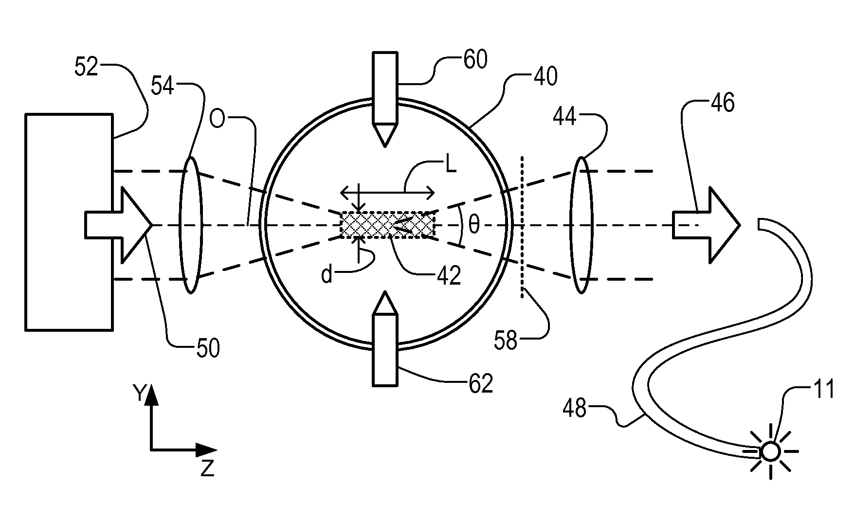
A laser driven light source comprises laser and focusing optics. These produce a beam of radiation focused on a plasma forming zone within a container containing a gas (e.g., Xe). Collection optics collects photons emitted by a plasma maintained by the laser radiation to form a beam of output radiation. Plasma has an elongate form (L>d) and collecting optics is configured to collect photons emerging in the longitudinal direction from the plasma. The brightness of the plasma is increased compared with sources which collect radiation emerging transversely from the plasma. A metrology apparatus using the light source can achieve greater accuracy and/or throughput as a result of the increased brightness. Back reflectors may be provided. Microwave radiation may be used instead of laser radiation to form the plasma.

Description

CROSS REFERENCE TO RELATED APPLICATIONS[0001]This application is related to U.S. Provisional Application No. 61 / 658,654, filed Jun. 12, 2012, which is incorporated by reference herein in its entirety.BACKGROUND[0002]1. Field of the Invention[0003]The present invention relates to plasma based photon sources. Such sources may be used for example to provide high brightness illumination in methods and for metrology usable, for example, in the manufacture of devices by lithographic techniques and to methods of manufacturing devices using lithographic techniques.[0004]2. Background Art[0005]Photon sources according to the invention may find application in a wide range of situations. As an example application, we will describe use of the invention as a light source in metrology. As a particular field of application of metrology, we shall refer for the sake of example to metrology in the manufacture of devices by lithography. The terms ‘light’ and ‘light source’ may be used conveniently to ...

Claims


Application Information

Patent Timeline
Patent Type & Authority Applications(United States)
IPC IPC(8): H05H1/24G03F7/20
CPCH05H1/24G03F7/20G01N21/956G03F7/70033G03F7/70616G03F7/70641H01J65/04H05G2/003H05G2/008H01J61/545H05B41/38G03F7/706847H01J61/02H01J61/54G01N2201/061
Inventor PELLEMANS, HENRICUS PETRUS MARIAANTSIFEROV, PAVEL STANISLAVOVICHKRIVTSUN, VLADIMIR MIHAILOVITCHDE WIT, JOHANNES MATHEUS MARIESMEETS, RALPH JOZEF JOHANNES GERARDUS ANNA MARIAVAN DER ZOUW, GERBRAND
Owner ASML NETHERLANDS BV
Why Eureka
Try Eureka