Light source apparatus and lighting apparatus

a technology of light source apparatus and light source, which is applied in the direction of light source devices, semiconductor lasers, lighting and heating apparatus, etc., can solve the problem of phosphor which generates fluorescence from the light of the laser diode deterioration fast, and achieve the effect of easy removal of hea

Inactive Publication Date: 2013-12-12
NITTO DENKO CORP
View PDF6 Cites 48 Cited by
  • Summary
  • Abstract
  • Description
  • Claims
  • Application Information

AI Technical Summary

Benefits of technology

[0004]The present invention is intended for a light source apparatus and a lighting apparatus,

Problems solved by technology

Further, since light emitted from the laser diode has a large amount of energy, a phos

Method used


Image

  • Light source apparatus and lighting apparatus
  • Light source apparatus and lighting apparatus
  • Light source apparatus and lighting apparatus

Examples


Embodiment Construction

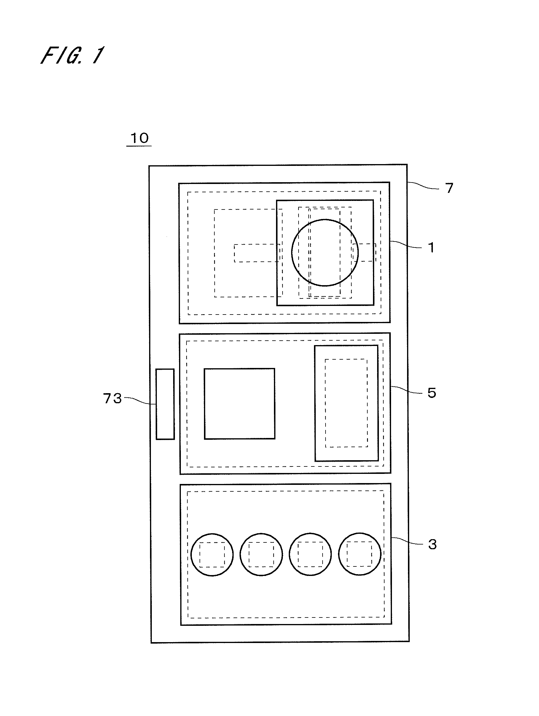
[0031]FIG. 1 is a plan view showing a lighting apparatus 10 in accordance with a first preferred embodiment of the present invention. The lighting apparatus 10 includes a laser lighting module 1, an LED (Light Emitting Diode) lighting module 3, and a sensor module 5. The lighting apparatus 10 further includes a mount body part 7 on which the laser lighting module 1, the LED lighting module 3, and the sensor module 5 can be removably mounted.

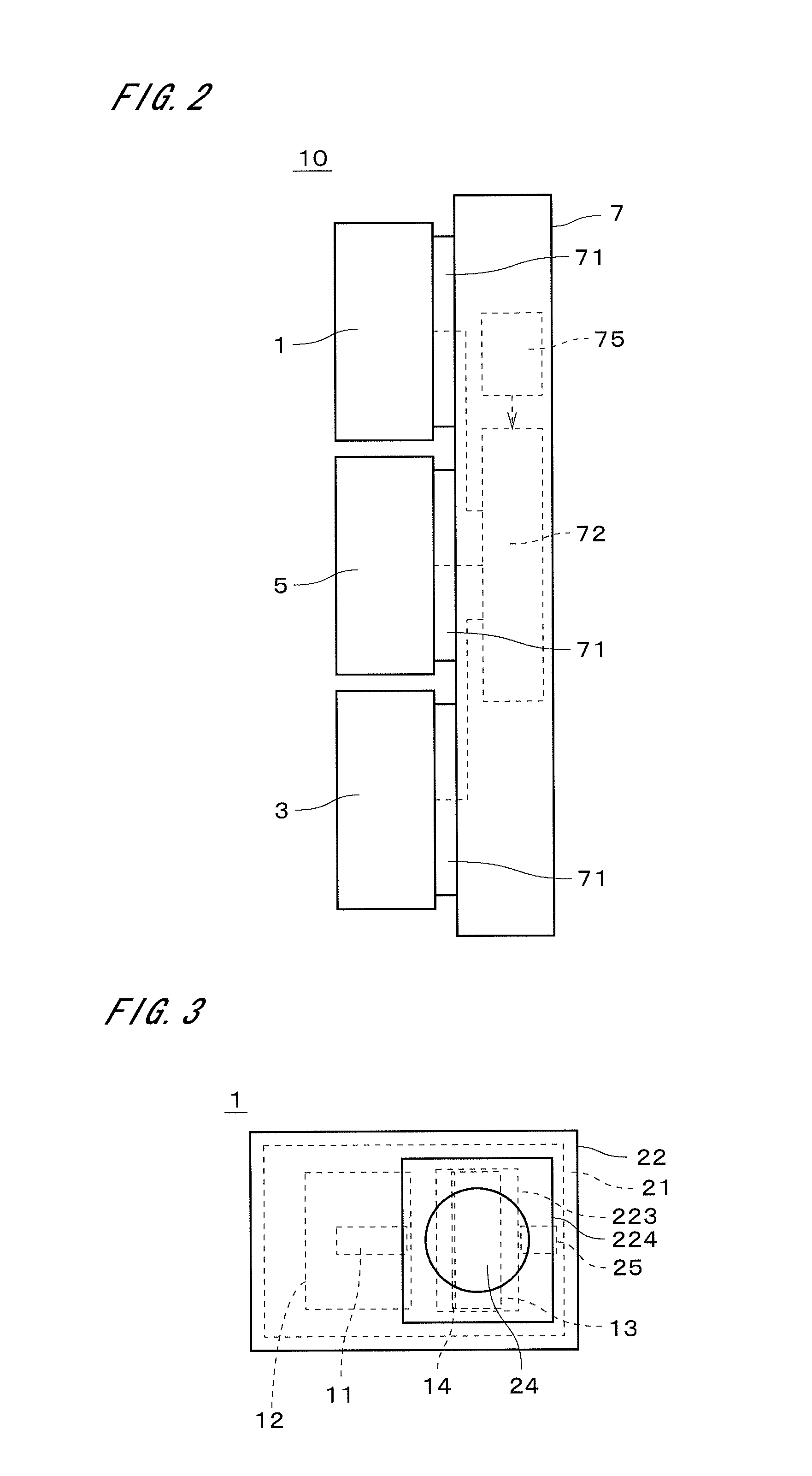
[0032]FIG. 2 is a side elevation showing the lighting apparatus 10. The mount body part 7 includes a plurality of (three, in the present preferred embodiment) module mount parts 71 on each of which any one of the laser lighting module 1, the LED lighting module 3, and the sensor module 5 can be mounted. The mount body part 7 further includes therein a common power supply 72 for commonly supplying the laser lighting module 1, the LED lighting module 3, and the sensor module 5 with electric power.

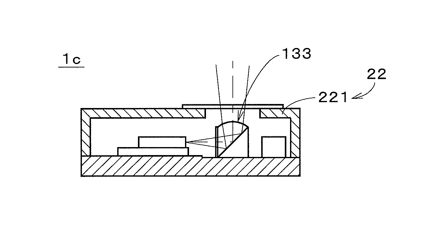
[0033]FIG. 3 is a plan view showing the laser lighti...


PUM


Abstract

A laser lighting module includes a base part, a laser diode which is a blue laser device, a substrate with which the laser diode is in contact, a ceramic phosphor which reflects light entering from the laser diode to thereby change a direction of the light and is excited by the light to generate yellow fluorescence, and a lens for adjusting luminous intensity distribution of light emitted from the ceramic phosphor. The substrate is formed of a material which is thin and has excellent thermal conductivity, and is in surface contact with the laser diode and the base part. In the laser lighting module, since the substrate serves as a device heat radiator, it is possible to easily remove the heat generated by the laser diode.

Description

TECHNICAL FIELD[0001]The present invention relates to a light source apparatus and a lighting apparatus.BACKGROUND ART[0002]In recent years, lighting apparatuses using LEDs (Light Emitting Diodes) as a light source have been used in offices, stores, and the like. On the other hand, a laser diode (LD) is used as a light source of an optical pickup of an optical drive, a laser beam printer, a laser pointer, and the like. For example, Japanese Patent Application Laid Open Gazette No. 2011-215531 (Document 1) discloses a projector including a light source which emits laser light. In the projector, a phosphor is disposed on an optical path between the light source and a cross dichroic prism. In a measurement endoscope disclosed in Japanese Patent Application Laid Open Gazette No. 2007-205918 (Document 2) and an internal measurement device disclosed in Japanese Patent Application Laid Open Gazette No. 2007-33298 (Document 3), a fluorescent material is disposed on a light outgoing surface ...

Claims


Application Information

Patent Timeline
IPC IPC(8): F21V29/00F21V9/16
CPCF21V29/002F21V9/16F21V5/04F21V13/04F21V13/14F21V29/505F21V29/507F21V29/70F21K9/64F21Y2115/10F21Y2115/30F21K9/60F21V7/26F21V9/38G02B5/04H01S5/0071H01S5/02208H01S5/0683H01S5/0087H01S5/02253H01S5/02325H01S5/024H01S5/06
Inventor SHIMIZU, HIROKAZUTANIUCHI, TETSUOFUJITA, TOSHIHIROTOKUDA, JUNMAEDA, SHIGEOITO, HISATAKAKATAYAMA, HIROYUKI
Owner NITTO DENKO CORP
Why Eureka
Try Eureka