Device for blowing air by means of narrow slit nozzle assembly

a technology of nozzle assembly and nozzle, which is applied in the direction of piston pumps, lighting and heating apparatus, heating types, etc., can solve the problems of only being able to adjust the pitch of fans or circulators, failing to meet the requirement for adjusting the direction of air stream, and reducing the brightness of the room, so as to save space

Inactive Publication Date: 2013-12-12
DYSON TECH LTD
View PDF6 Cites 47 Cited by
  • Summary
  • Abstract
  • Description
  • Claims
  • Application Information

AI Technical Summary

Benefits of technology

[0036]An airflow passage is connected between the nozzle assembly and the base seat in this invention. An intake end of the airflow passage is opened on the outer surface of the base seat, and an output end is connected to the nozzle assembly by means of a pivot component. The base seat supplies an air stream to the nozzle assembly by way of the airflow passage. Two pivot components are connected between the nozzle assembly and the base seat, and the nozzle assembly is rotatably connected to the base seat by the two pivot components, thereby realizing pitch rotation of the nozzle assembly around base seat at a large angle and satisfying the demands for adjustment of jet direction of the air stream. Furthermore, when the device for blowing air is idle, the nozzle assembly can be rotated and folded to a flat state so as to save space.

Problems solved by technology

The conventional home fan has the disadvantages that the air stream generated by the rotating blades or impeller cannot be uniformly sensed by the user, so the user has a feeling of “patting” generated by the turbulent airflow.
Moreover, the blades occupy a large area and thus lower the room brightness.
However, the pitch of the fan or circulator can only be adjusted at a small angle, which fails to satisfy the requirement for adjusting the direction of air stream at a large angle.
Meanwhile, in most circumstances, the fan operates by using an electric motor to drive the impeller directly, but usually the rotational speed of the electric motor cannot exceed 5000 rpm, which greatly limits the working efficiency.
The conventional bladeless fan is not provided with an air filter device at the air intake, so after a long time of use, the dusts in the air adhere to the impeller, pipes in the base, inner passage, and mouth of the nozzle.
Particularly, the structure inside the bladeless fan is complicated due to the structure of the impeller and is hard to disassemble for cleaning.
In the absence of the air filter device, an excessive amount of dust will adhere, which adds to the load on the electric motor for driving the impeller and in turn shortens the operational lifespan and increases the energy consumption.
Meanwhile, the excessive dust may block the slit of the nozzle so that the nozzle cannot jet the air stream, which in turn shortens the operational lifespan of the fan.
In view of the above, the conventional bladeless fan has obvious inconvenience and defects in use and needs to be improved and perfected.

Method used


Image

  • Device for blowing air by means of narrow slit nozzle assembly
  • Device for blowing air by means of narrow slit nozzle assembly
  • Device for blowing air by means of narrow slit nozzle assembly

Examples


Embodiment Construction

[0055]To make the objectives, technical solutions and advantages of this invention understandable clearly, the invention is described in further detail below in conjunction with the drawings and embodiments. It should be understood that the embodiments are described for explaining this invention only and are not intended to limit the scope of this invention.

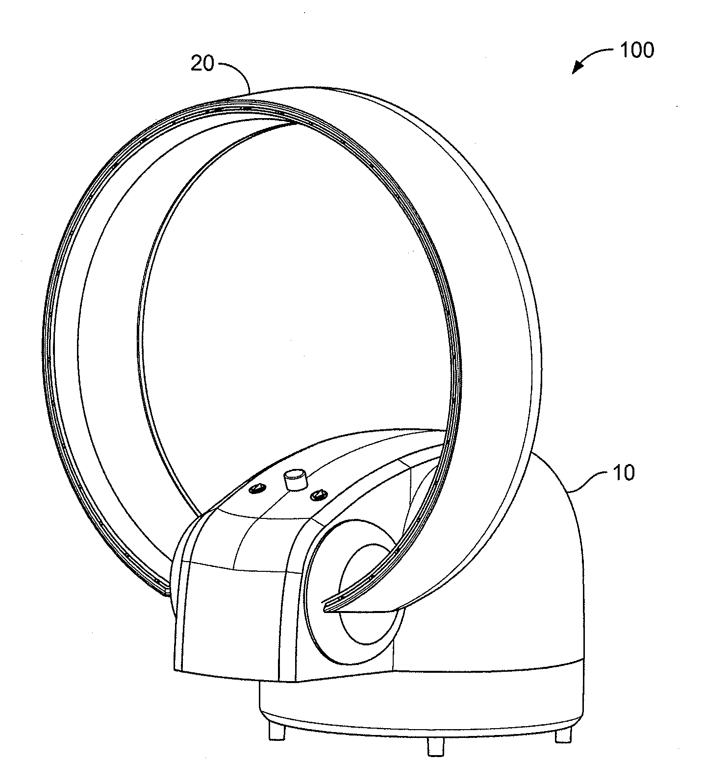
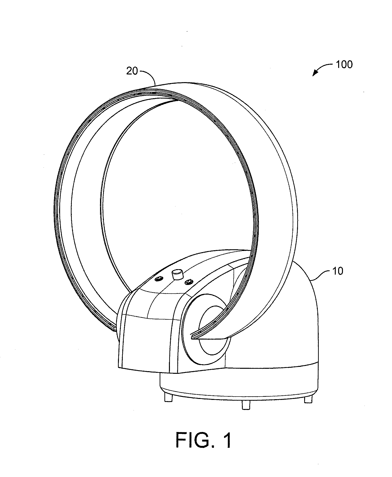
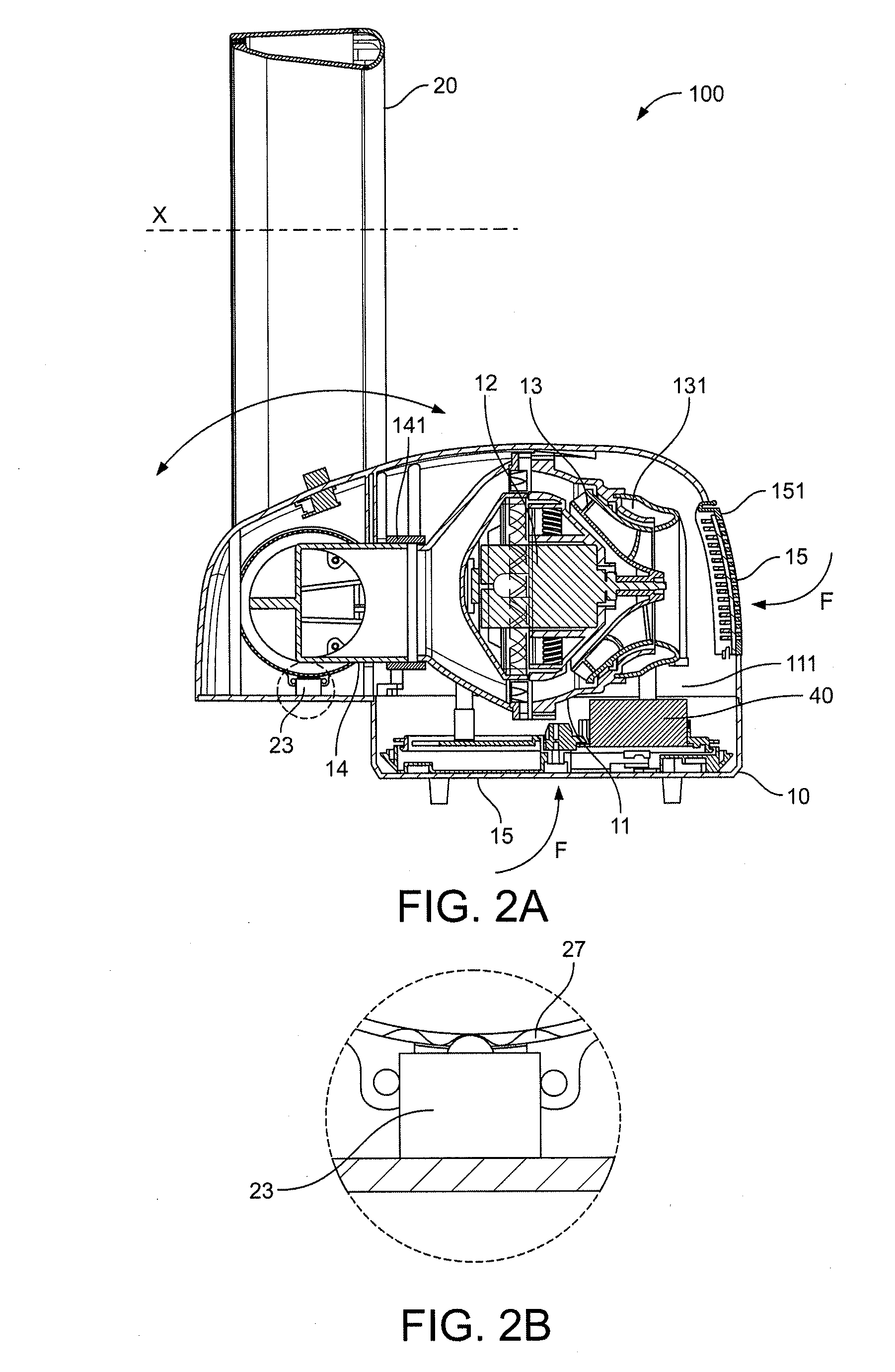
[0056]Referring to FIGS. 1-4, a device 100 for blowing air by means of a narrow slit nozzle assembly is provided. The device includes a base seat 10 for generating an air stream to supply air flow and a narrow slit nozzle assembly 20 supported by the base seat 10 for blowing air. An airflow passage is connected between the base seat 10 and the nozzle assembly 20. An intake end of the airflow passage is opened on the outer surface of the base seat 10, and an output end of the airflow passage is connected to the nozzle assembly 20 by means of a pivot component 21. An intake end of the nozzle assembly 20 is connected to an output en...


PUM


Abstract

A device for blowing air by a narrow slit nozzle assembly is provided. The device includes a base seat for generating an air stream to supply air flow and a narrow slit nozzle assembly supported by the base seat for blowing air. An airflow passage is connected between the base seat and the nozzle assembly. An intake end of the airflow passage is opened on the outer surface of the base seat, and an output end is connected to the nozzle assembly by a pivot component. An intake end of the nozzle assembly is connected to an output end of the base seat by the pivot component. An impeller and an electric motor for driving the impeller to rotate are provided within the base seat. The nozzle assembly is rotatably fixed on the base seat by the pivot component. The rotation direction of the nozzle can be adjusted by the rotation of the pivot component around the airflow passage. And when the fan is idle, the nozzle can be folded so as to save space.

Description

REFERENCE TO RELATED APPLICATIONS[0001]This application is a continuation of International Application No. PCT / CN2011 / 074668, filed May 25, 2011, which claims the priority of Chinese Application No. 201020205107.7, filed May 27, 2010, Chinese Application No. 201020224739.8, filed Jun. 12, 2010, Chinese Application No. 201020519265.X, filed Sep. 7, 2010, and Chinese Application No. 201020536812.5, filed Sep. 20, 2010, the entire contents of which are incorporated herein by reference.FIELD OF THE INVENTION[0002]The present invention relates to a pumping device or system for pumping an elastic fluid by a rotary pump, in particular to a ventilation device or system in which the working fluid is air, and more particularly to a device for blowing air by means of a narrow slit nozzle where the jetting direction of the device can be adjusted in a large range.BACKGROUND OF THE INVENTION[0003]A home fan usually includes a rotary shaft, a set of blades or an impeller rotating around the shaft,...

Claims


Application Information

Patent Timeline
Patent Type & Authority Applications(United States)
IPC IPC(8): F04D13/06
CPCF04D13/06F04D25/08F04D25/105F04F5/16F04D29/70F24F13/28B05B9/01F04D25/10F04F5/461
Inventor LI, DEZHENG
Owner DYSON TECH LTD
Why Eureka
Try Eureka