
Device for inspecting a steam generator

a steam generator and inspection device technology, applied in the direction of steam boiler components, color television, television systems, etc., can solve the problems of oscillation phenomena, cracks in the tubes, and appearance of leakage between the primary and secondary circuits

Inactive Publication Date: 2013-12-19
SRA SAVAC
View PDF11 Cites 8 Cited by
  • Summary
  • Abstract
  • Description
  • Claims
  • Application Information

AI Technical Summary

Benefits of technology

The patent describes a device that uses magnetic field coupling to inspect and clean the interior of a flow tube. The device includes a first probe driven by a second probe and guided along the flow tube. The first probe can access different fluid passage openings and the shape of the fouling can be easily identified through the televisional images. The device also has air propulsion means to clean the video lens and ensure optimal inspection of the flow tube. The technical effects of the device include improved clogging level estimation and better prevention of blockages.

Problems solved by technology

The tubes and other metal parts of the cyclone separator are then subjected to extreme conditions that inevitably cause corrosion.
Without intervention, deposits related to this corrosion build up on the tubular plate 7 and the spacer plates 8, and may in particular at least partially clog the aforementioned passage areas, which is detrimental to the output of the steam generator, as well as the operating safety thereof if the clogging level reaches a high value.
In fact, a high clogging rate may lead to the appearance of excessive vibrations of the tubes in certain areas of the steam generator, these vibrations potentially leading to the quick development of cracks of the tubes and therefore the appearance of leaks between the primary and secondary circuits.
Such a high clogging rate may also cause oscillation phenomena at the water in the secondary circuit, and significant mechanical forces on the spacer plates, the flow tubes and the inner enclosure.
However, such an inspection system only makes it possible to view the clogging in the passage areas, from above, but does not make it possible to obtain information on the shape of the clog at the plate inlet, i.e., in the circulation direction of the fluid in the secondary circuit, which may lead to a poor estimate of the clogging level.

Method used


Image

  • Device for inspecting a steam generator
  • Device for inspecting a steam generator
  • Device for inspecting a steam generator

Examples


Embodiment Construction

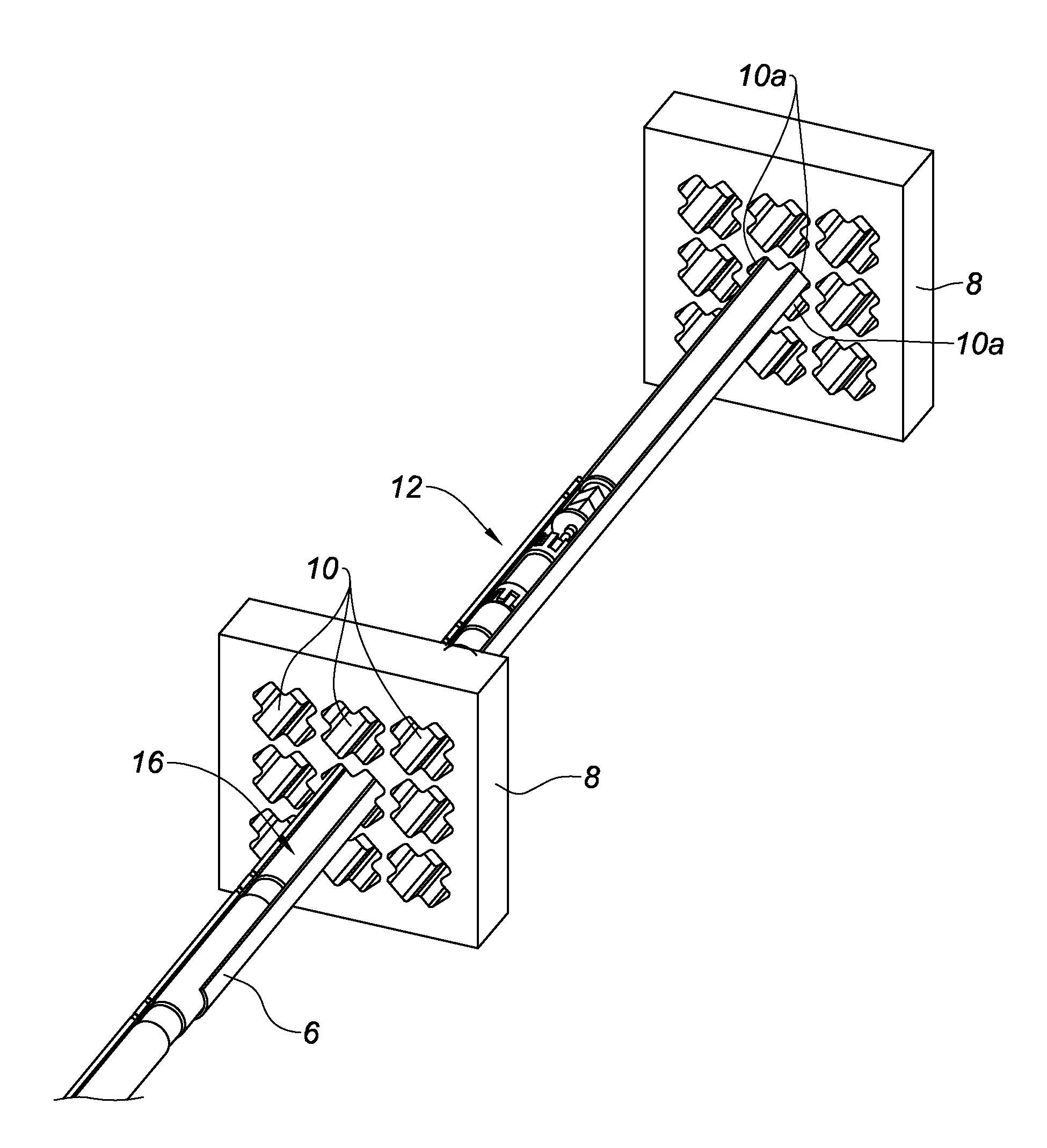
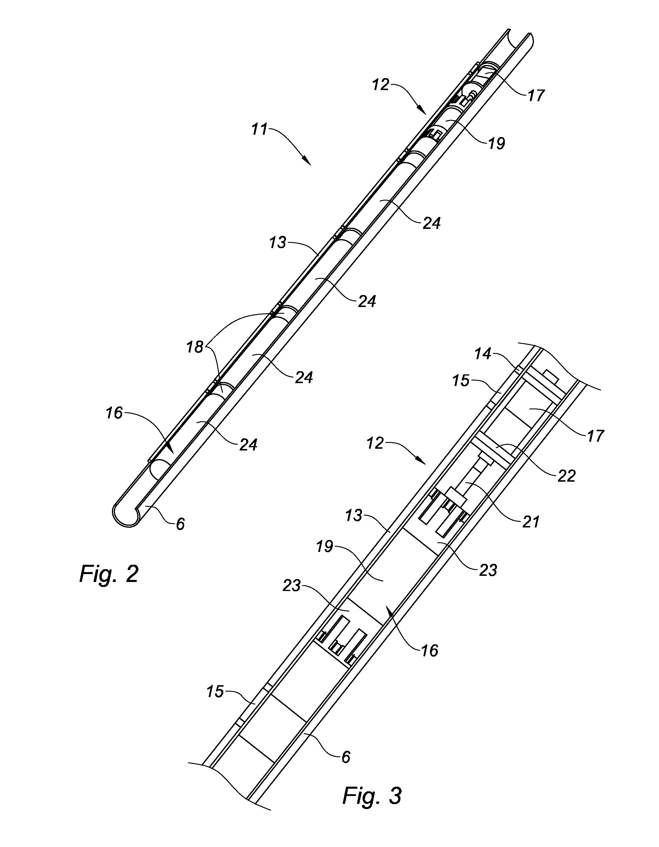
[0057]The inspection device 11 includes a first long and flexible video probe 12. The first video probe 12 is advantageously a fiberscope, and for example has a diameter of approximately 2 mm. The first video probe 12 comprises an outer sheath 13 at the distal end of which a head 14 is mounted equipped with a video lens (not shown in the figures). The first video probe 12 further comprises lighting means (not shown in the figures) arranged to light an area positioned near the distal end of the first probe.

[0058]The lighting means advantageously include at least one optical fiber or optical fiber bundle extending inside the outer sheath 13 substantially over the entire length thereof. The or each optical fiber includes a first end connected to a light source (not shown in the figures) and a second end emerging at the distal end of the first probe.

[0059]The second end of the or each optical fiber is preferably oriented so as to cause the light from the light source to converge in an a...


PUM


Abstract

An inspection device for inspecting a steam generator having a first long and flexible video probe intended to be inserted inside the housing of the steam generator and configured to be moveable through a fluid passage orifice defined by a spacer plate and a flow tube, all arranged inside the housing. The first video probe includes at least one ferromagnetic element. The inspection device also includes a second long and flexible probe to be inserted into a flow tube, the second probe including at least one permanent magnet arranged to cooperate with the at least one ferromagnetic element of the first probe so that the first probe can be driven along the exterior surface of a flow tube by the second probe when the second probe is inserted into the flow tube and moved therein, and when the first probe is inserted into the housing of the steam generator and positioned near the exterior surface of the flow tube in which the second probe is inserted.

Description

FIELD OF THE INVENTION [0001]The present invention relates to a device for inspecting a steam generator.BACKGROUND OF THE INVENTION [0002]Steam generators are in particular used in nuclear power plants, where they form heat exchangers including two distinct circuits, respectively a primary circuit in which hot water circulates at a very high pressure coming from the reactor, and a secondary circuit in which the water is brought to boil. The steam thus formed then escapes from the steam generator and is used to rotate turbines coupled to an alternator.[0003]FIG. 1 shows part of a steam generator 1 assuming the form of a cylindrical housing including a lower portion 2 designed for connection of the primary circuit, and an upper portion 3 designed for the outlet of the steam and drying thereof.[0004]The steam generator 1 includes an outer enclosure called a shroud 4 and an inner enclosure called an enclosure skirt 5. Metal flow tubes 6 are positioned in the volume delimited by the encl...

Claims


Application Information

Patent Timeline
Patent Type & Authority Applications(United States)
IPC IPC(8): G21C17/007G21C17/017G21C17/01
CPCG21C17/007G21C17/01G21C17/017F22B37/003G21C17/003G21D1/006Y02E30/00Y02E30/30
Inventor MANDIER, JEAN-PAULDE OLIVEIRA, JORGEFANJAS, LAURENT
Owner SRA SAVAC
Learn More