Method and system for determining an ego-motion of a vehicle

a vehicle and ego-motion technology, applied in the field of vehicle ego-motion determination, can solve the problems of limiting the utility of corresponding systems during assisted parking or navigation in an unclear surroundings, not very accurate or complex methods for collision protection and obstacle detection described above, etc., to achieve the effect of increasing the complexity of parking assistants, improving the calculation of vehicle ego-motion, and increasing the accuracy of parking assistants

Active Publication Date: 2013-12-19
ROBERT BOSCH GMBH
View PDF12 Cites 44 Cited by
  • Summary
  • Abstract
  • Description
  • Claims
  • Application Information

AI Technical Summary

Benefits of technology

[0017]Among other things, the present invention is based on the idea of improving the calculation of the ego-motion of a vehicle in a simple manner, by drawing upon data of a vehicle camera for the determination of the ego-motion, for instance, the data of a rearview camera. In the systems known up to now, images of a vehicle camera are used only for obstacle detection, and not for determining the vehicle's ego-motion; the latter is rather determined based on sensors independent of the surroundings, such as wheel state sensors and steering angle sensors, or via GPS, gyroscope and the like.
[0018]The present invention leads to an increase in the accuracy of parking assistants, collision warning systems, etc., without increasing their complexity excessively. An improved accuracy in the determination of an ego-motion is helpful, for example, in the calculation, monitoring and adjustment of a parking/unparking trajectory, so as to achieve “gentle” parking in response to automatic guidance, for a collision warning, etc. These advantages are achieved, in part, in that, based on the improved accuracy in the determination of the ego-motion, lower safety distances from objects or potential obstacles along a travel route envelope or a trajectory during parking and unparking, navigating in a cramped surroundings such as a parking garage, etc., are required.
[0019]The more accurate determination of the vehicle's ego-motion makes possible an improved guidance of

Problems solved by technology

The methods for collision protection and obstacle detection described above are either not very accurate or they are complex.
However, if the complexity of a parking assistant, for example, is to remain limited for reasons of cost, this can only be achieved in that, for example

Method used


Image

  • Method and system for determining an ego-motion of a vehicle
  • Method and system for determining an ego-motion of a vehicle
  • Method and system for determining an ego-motion of a vehicle

Examples


Embodiment Construction

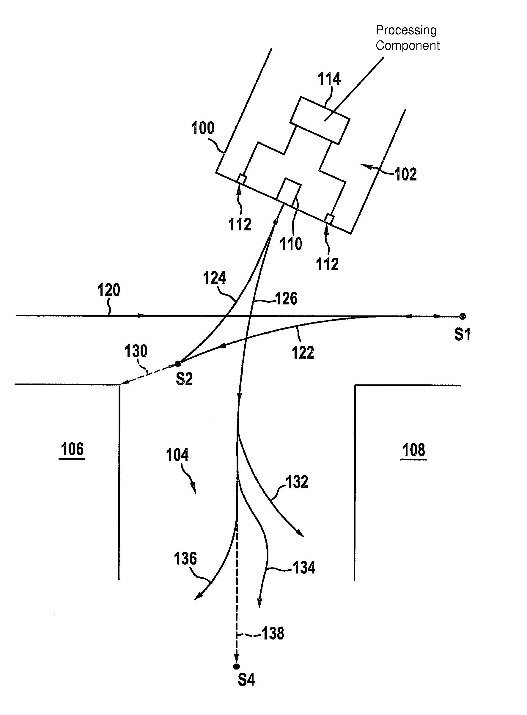
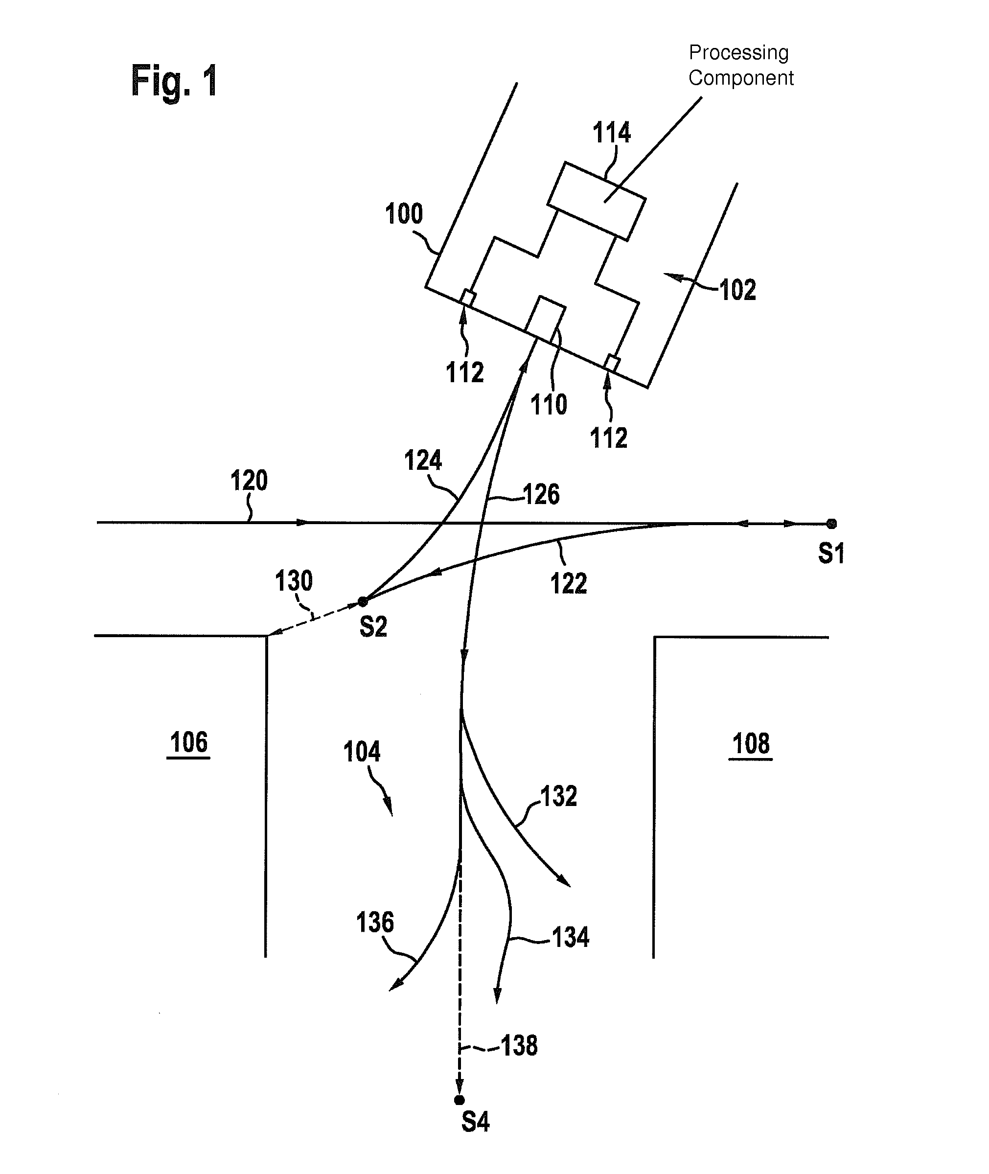
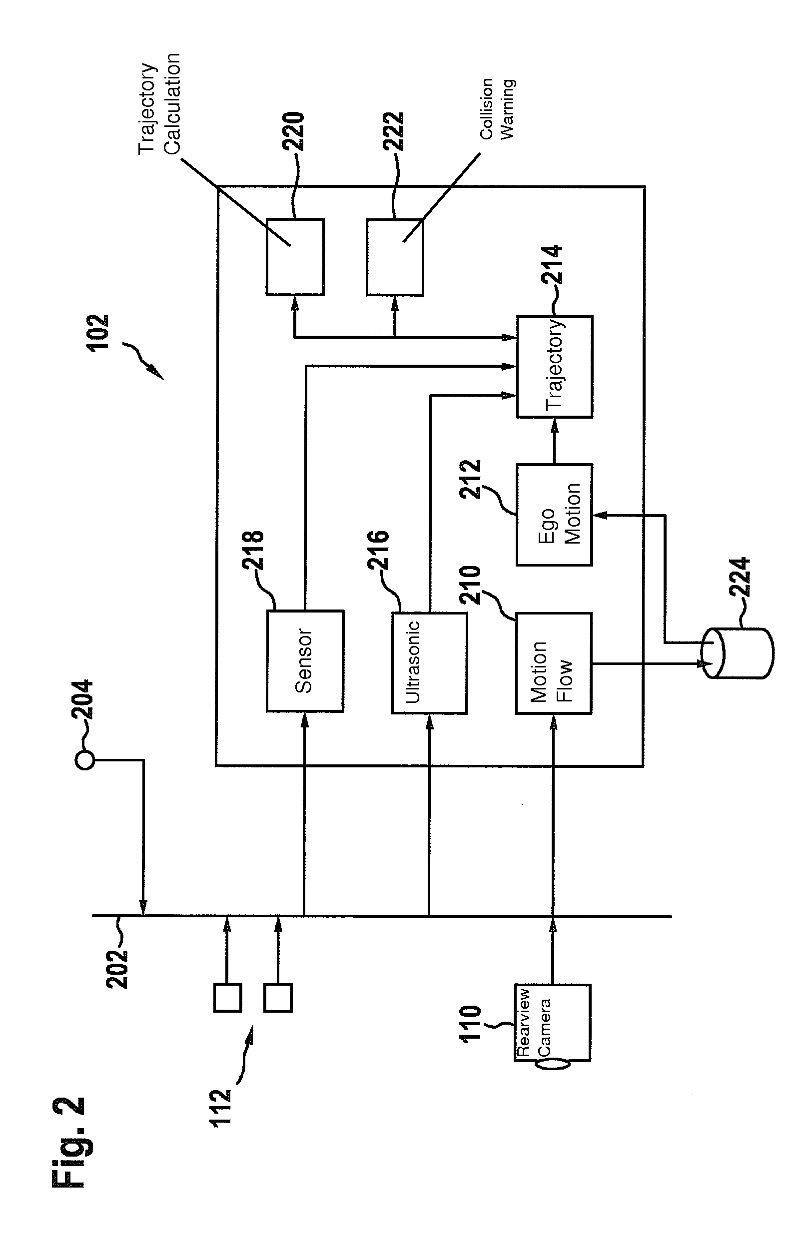
[0025]FIG. 1 illustrates in schematic form a vehicle 100 equipped, according to the present invention, with a driver assistance system 102 in an exemplary parking situation, in which the vehicle 100 is to be parked backwards in a parking space 104 between parking space-limiting objects 106 and 108, which may be parking vehicles, for example. Driver assistance system 102 has a camera 110 implemented as a rearview camera, as well as a set of ultrasonic sensors 112. All the sensors 110, 112 are connected via a vehicle network (not shown) to a central processing component 114, which is implemented as an ECU (“electronic control unit”).

[0026]Vehicle 100 first moves along path 120, past parking space 104, the latter being measured by additional sensors (not shown) of driver assistance system 102. The driver decides to park, whereupon the vehicle stops at stopping point S1. From this point on, a parking assistant (a subsystem of driver assistance system 102) takes over the further parking ...


PUM


Abstract

A method for determining an ego-motion of a vehicle is described, which is carried out in driver assistance systems, particularly in parking assistance systems. The method involves: taking a sequence of images, successive in time of a vehicle surroundings by a vehicle camera; determining, based on the image sequence, at least one motion flow with regard to an object in the vehicle surroundings; and determining the ego-motion of the vehicle based on the at least one motion flow.

Description

FIELD OF THE INVENTION[0001]The present invention relates to a method for determining an ego-motion (self-movement) of a vehicle, which is carried out in driver assistance systems, particularly in parking assistance systems.BACKGROUND INFORMATION[0002]Driver assistance systems are used to assist the driver in certain driving situations. A driver assistance system may include, for example, an ABS (antilock system), ESP (electronic stability program), a distance-regulating cruise controller (“adaptive cruise control”, ACC), and / or a parking assistant for assisting parking or unparking (leaving a parking space). For at least some of the driver assistance subsystems, determining a vehicle ego-motion is also required. This is so, for instance, in a system for collision-warning, which is based on a prediction as to whether, in response to the continuation of the instantaneous vehicle motion, a collision will occur or not. Parking assistants require data for the instantaneous actual vehicl...

Claims


Application Information

Patent Timeline
IPC IPC(8): B60Q9/00
CPCB60Q9/005B62D15/0285G06T2207/30264G06T7/269B60Q9/008
Inventor HEGER, THOMASSIMON, STEPHANHELMLE, MICHAEL
Owner ROBERT BOSCH GMBH
Why Eureka
Try Eureka