

Wind energy system and method for using same
a technology of wind energy and wind energy, applied in the field of wind energy, can solve the problems of increasing driveline maintenance, increasing the cost and complexity of maintenance actions, and inability to sustain energy supply
- Summary
- Abstract
- Description
- Claims
- Application Information
AI Technical Summary
Benefits of technology
Problems solved by technology
Method used
Image

Examples
Embodiment Construction
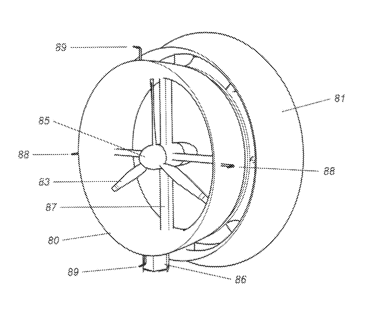
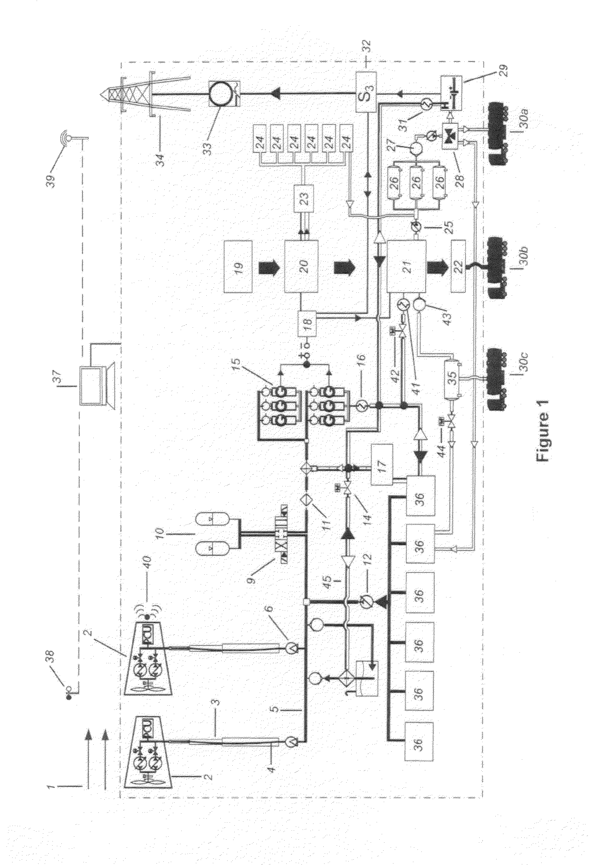
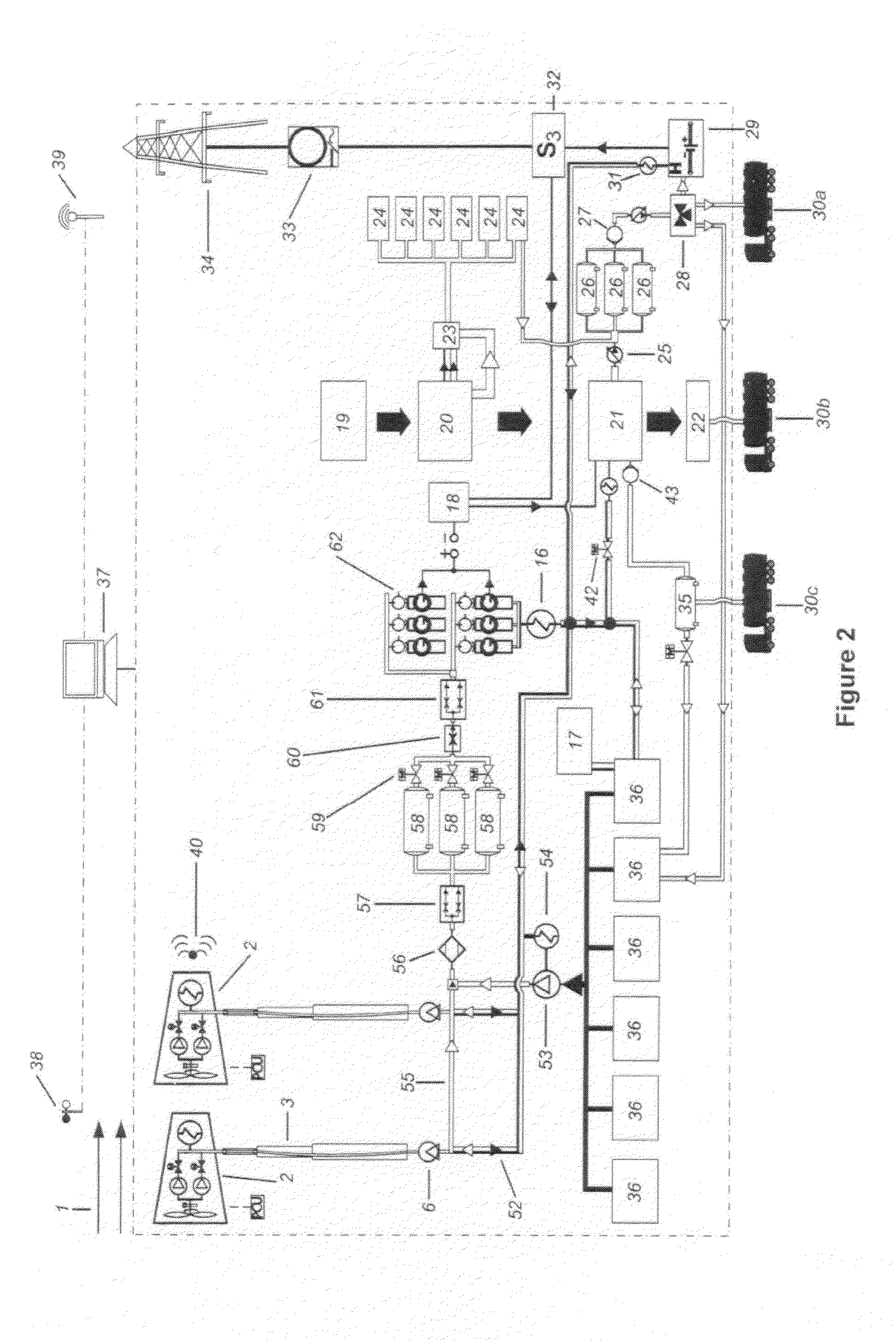
[0192]FIG. 1 is a schematic diagram of the wind energy system of the present invention. Specifically, FIG. 1 shows the process by which the sustainable energy system (SES) of the present invention extracts energy from wind through a decoupled multiple rotor ducted diffuser wind turbine by converting the energy from the prevailing wind into rotational energy of the rotor blades. The rotational energy captured by the rotor blades drives a series of hydraulic pumps that transfer the rotational energy into a pressurized fluid. The pressurized fluid transmits, balances and stores the captured energy in hydraulic accumulators, which retain the energy under pressure that can then be released through valves in a controlled manner.
[0193]The fluid pressure is maintained in the accumulators by a membrane bladder (diaphragm), steel piston or steel bellows. Each of these options uses the hydraulic pressure to force the bladder, piston or bellows against a gas, which compresses under the pressure...
PUM
| Property | Measurement | Unit |
|---|---|---|
| operating pressure | aaaaa | aaaaa |
| particle sizes | aaaaa | aaaaa |
| speeds | aaaaa | aaaaa |
Abstract
Description
Claims
Application Information